
Liquid crystal drive apparatus and gradation display method
a technology of liquid crystal drive and display method, which is applied in the direction of static indicating devices, non-linear optics, instruments, etc., can solve the problem that the conventional liquid crystal drive apparatus is not sufficient to drive liquid crystals at high speed, and achieve the effect of high speed
Patent Information
- Authority / Receiving Office
- US · United States
- Patent Type
- Patents(United States)
- Current Assignee / Owner
- Publication Date
- 2006-10-10
- Estimated Expiration
- Not applicable · inactive patent
Smart Images
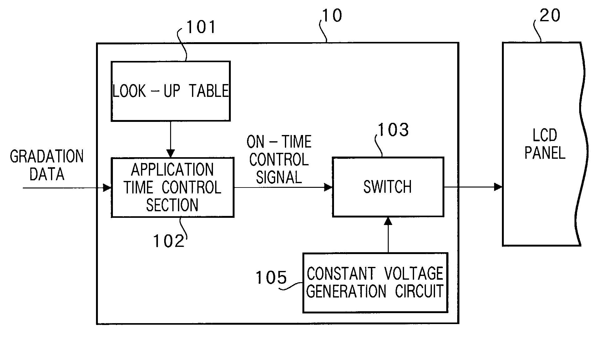
Figure 1 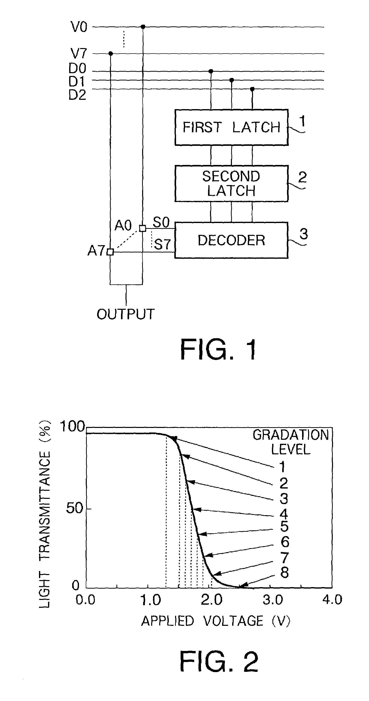
Figure 2 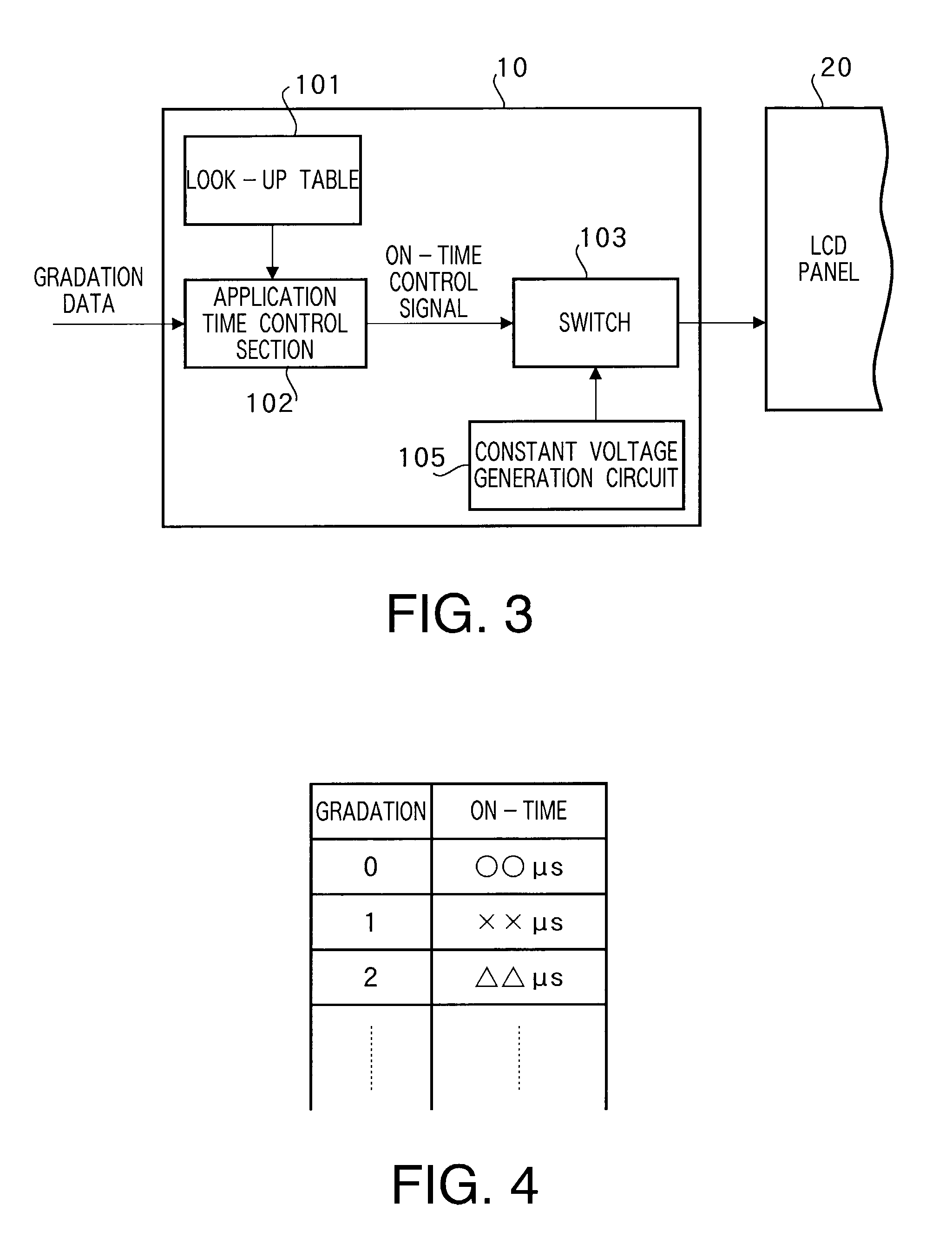
Figure 3
Abstract
Description
TECHNICAL FIELD
[0001] The present invention relates to a liquid crystal drive apparatus and gradation display method, and more particularly, to a liquid crystal drive apparatus and gradation display method according to a new gradation display system.BACKGROUND ART
[0002] An active matrix type liquid crystal display apparatus producing a multi-gradation display is known in the prior art. This multi-gradation display is performed by selecting one reference voltage corresponding to the gradation display data from among as many reference voltages as display gradations using an analog switch and driving the liquid display apparatus at the selected reference voltage.
[0003] FIG.1 is a block diagram showing a conventional liquid crystal drive apparatus for driving an active matrix type liquid crystal display apparatus. This liquid crystal drive apparatus is provided with first latch 1, second latch 2 and decoder 3 for every vertical pixel line of the liquid crystal display apparatus.
[0004] First...
Examples
embodiment 1
(Embodiment 1)
[0037]FIG. 3 is a block diagram showing an outlined configuration of a liquid crystal drive apparatus according to Embodiment 1 of the present invention. Liquid crystal drive apparatus 10 according to Embodiment 1 is provided with application time control section 102 that controls a voltage application time according to gradation data, look-up table 101 that associates gradation with application time (ON-time) and switch 103 that outputs a constant voltage generated by constant voltage generation circuit 105 to LCD panel 20 according to the ON-time control signal output from application time control section 102.
[0038]As shown in FIG. 4, look-up table 101 is a table that associates a gradation level with an application time during which the switch is ON. Here, a gradation display of the liquid crystal drive apparatus according to the present invention will be explained using FIG. 5 to FIG. 7.
[0039]FIG. 5 illustrates a relationship between light transmittance and time, F...
embodiment 2
(Embodiment 2)
[0053]FIG. 9 is a block diagram showing an outlined configuration of a liquid crystal drive apparatus according to Embodiment 2 of the present invention. The liquid crystal drive apparatus according to Embodiment 2 is provided with application time control section 102 that controls a voltage application time according to gradation data, pattern table 104 that associates a gradation with an application time (ON-pattern) and switch 103 that outputs a constant voltage generated by constant voltage generation circuit 105 to LCD panel 20 according to an ON pattern control signal output from application time control section 102.
[0054]As shown in FIG. 10, pattern table 104 is a table that associates a gradation level with an application pattern for turning ON the switch. As applied patterns, there can be, for example, patterns whereby a predetermined liquid crystal drive time as shown in FIG. 11 is divided into a plurality of blocks at which application or non-application of ...
embodiment 3
(Embodiment 3)
[0066]This embodiment sets a voltage application time (or voltage application pattern) corresponding to a gradation considering the area obtained by integrating the amount of transmitted light of liquid crystals at various points in time over an LED light emission period when a maximum rated voltage of the liquid crystals is applied. More specifically, as shown in FIG. 12, the area (area indicated by hatching of the drawing) obtained by integrating the waveform amount of transmitted light that penetrates the liquid crystals when a drive voltage is applied over the LED light emission period is associated with each gradation.
[0067]That is, the liquid crystals are driven in such a way that the area of the hatching area in FIG. 12 increases as the input gradation data shows higher gradations. Since the applied voltage is actually set to be constant at a maximum rated voltage of the liquid crystals, the area of the hatching is changed according to the gradation by changing ...