
Scanning apparatus and method
a three-dimensional object and scanning apparatus technology, applied in the field of scanning apparatus and methods, can solve the problems of difficult scanning of real-world, three-dimensional objects, difficult line of sight, high cost of cnc machines, etc., and achieve the effect of reducing time and cost of generating and quickly scanning the surface of objects
Patent Information
- Authority / Receiving Office
- US · United States
- Patent Type
- Patents(United States)
- Current Assignee / Owner
- Publication Date
- 2007-12-25
- Estimated Expiration
- Not applicable · inactive patent
Smart Images
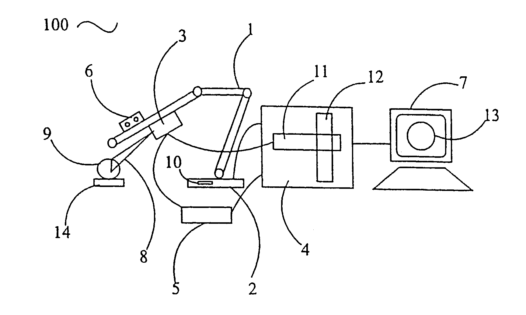
Figure 1 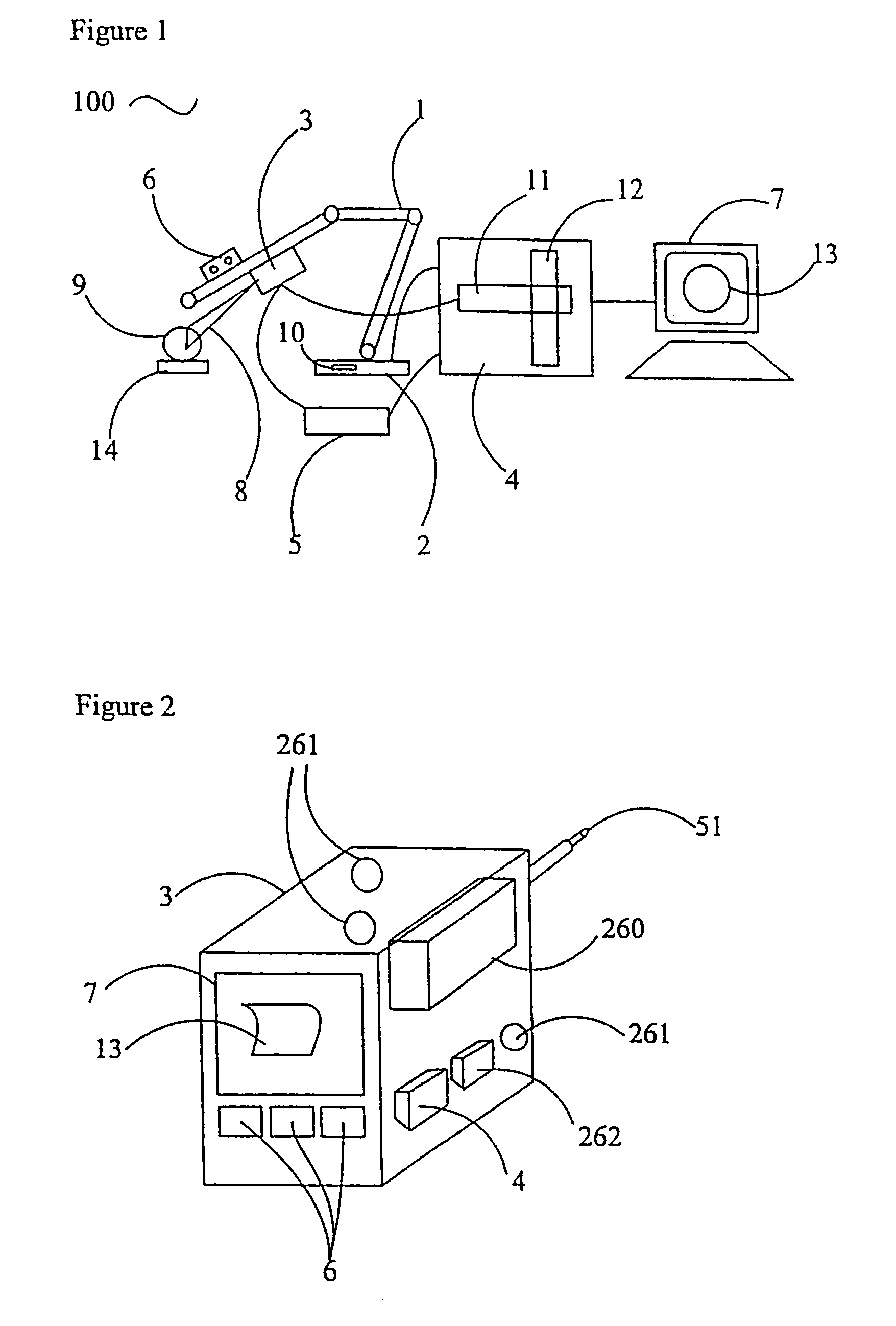
Figure 2 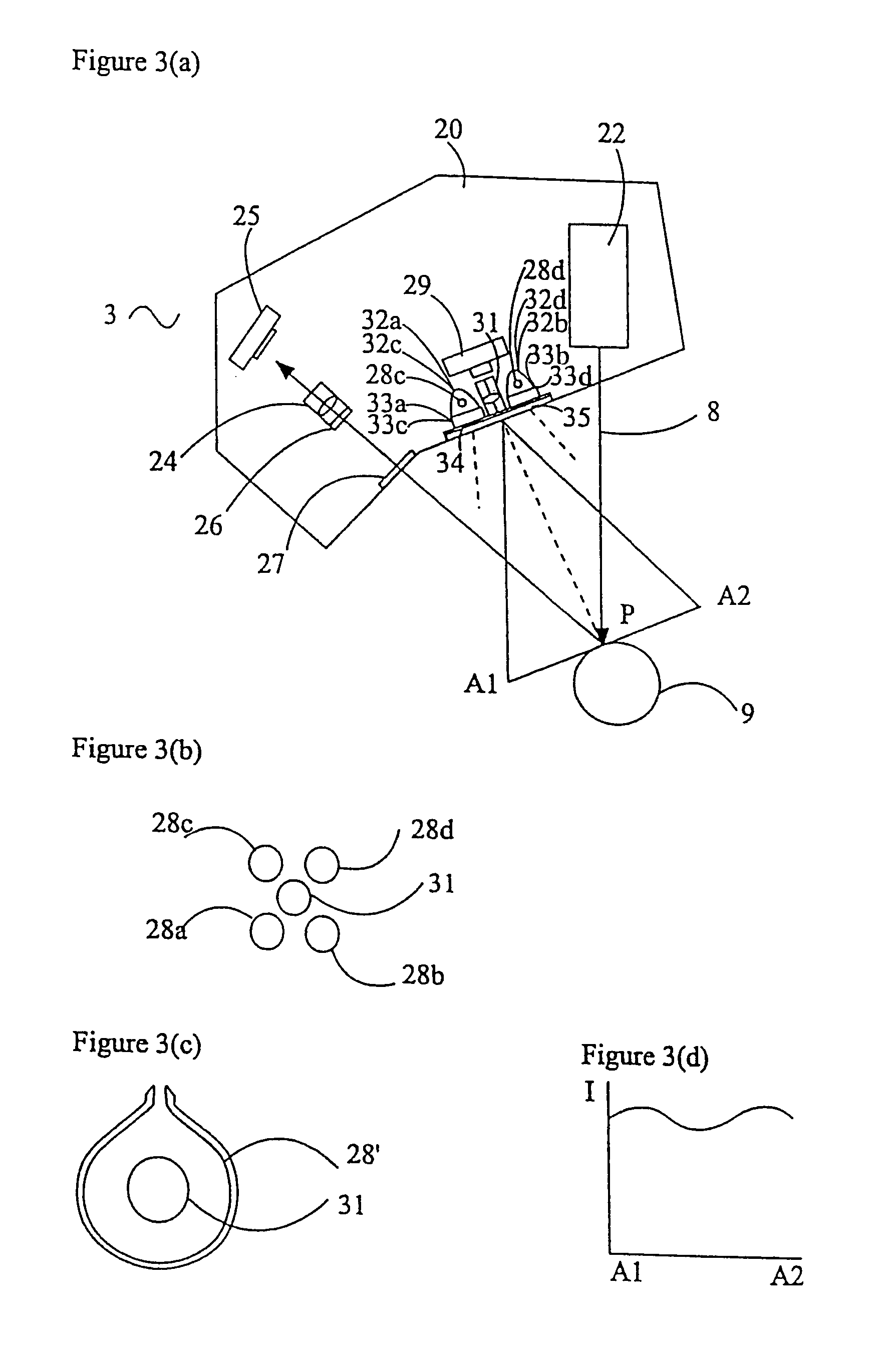
Figure 3
Abstract
Description
CROSS-REFERENCES TO RELATED APPLICATIONS
[0001] This application is a continuation of U.S. patent application Ser. No. 09 / 000,215, filed on May 26, 1998, now U.S. Pat. No. 6,611,617, which is a 371 of international application PCT / GB96 / 01868, filed Jul. 25, 1996, which in turn claims the benefit of British Application No. 9515311.0, filed Jul. 26, 1995.FIELD OF THE INVENTION
[0002] This invention relates to an apparatus and method for scanning a three-dimensional object.BACKGROUND OF THE INVENTION
[0003] Real-world, three-dimensional objects, whether with natural form (e.g., geographical, plant, human, or animal-like) or man-imagined form (e.g., sculptures, reliefs, cars, boats, planes, or consumer products) are difficult to scan. This is because of features such as rapidly varying surface normals and surfaces for which a line of sight is difficult because it is partially obscured by other parts of the object.
[0004] Scanning machines—also known as digitizing machines—for scanning objects o...
Examples
Embodiment Construction
[0080]Referring now to FIG. 1, a scanning apparatus 100 comprises a multiply-jointed arm 1 with an arm control unit 2 and a probe 3. The control unit 2, which includes a processing unit 10, is coupled to a computer or processing unit 4 and color monitor 7. The probe 3 is also coupled to a probe control unit 5 that is likewise coupled to the computer 4. The intermediate data is displayed on the color monitor 7 as rendered polygons 13. The probe 3 provides a stripe 8, which is projected onto an object 9 positioned on a turntable 14. The stripe 8 is in the form of a plane of light. Buttons 6 are also provided to control data capture. A color frame grabber 11 in the computer 4 is mounted on a standard bus 12 and coupled to the probe 3.
[0081]The computer 4, probe control unit 5, arm control unit 2, buttons 6, color frame grabber 11, and monitor 7 are provided separately. For example, the computer 4 and monitor 7 may be a personal computer and VDU, although for certain applications, it ma...