
Apparatus and method for controlling feed-forward amplifiers
a technology of amplifiers and amplifiers, applied in amplifiers, electrical equipment, amplifier modifications to reduce noise influence, etc., can solve the problems of signal cancellation loops that should first be nullled and not very useful, and achieve the effect of improving performance and maximising cancellation
Patent Information
- Authority / Receiving Office
- US · United States
- Patent Type
- Patents(United States)
- Current Assignee / Owner
- Publication Date
- 2008-03-11
- Estimated Expiration
- Not applicable · inactive patent
Smart Images
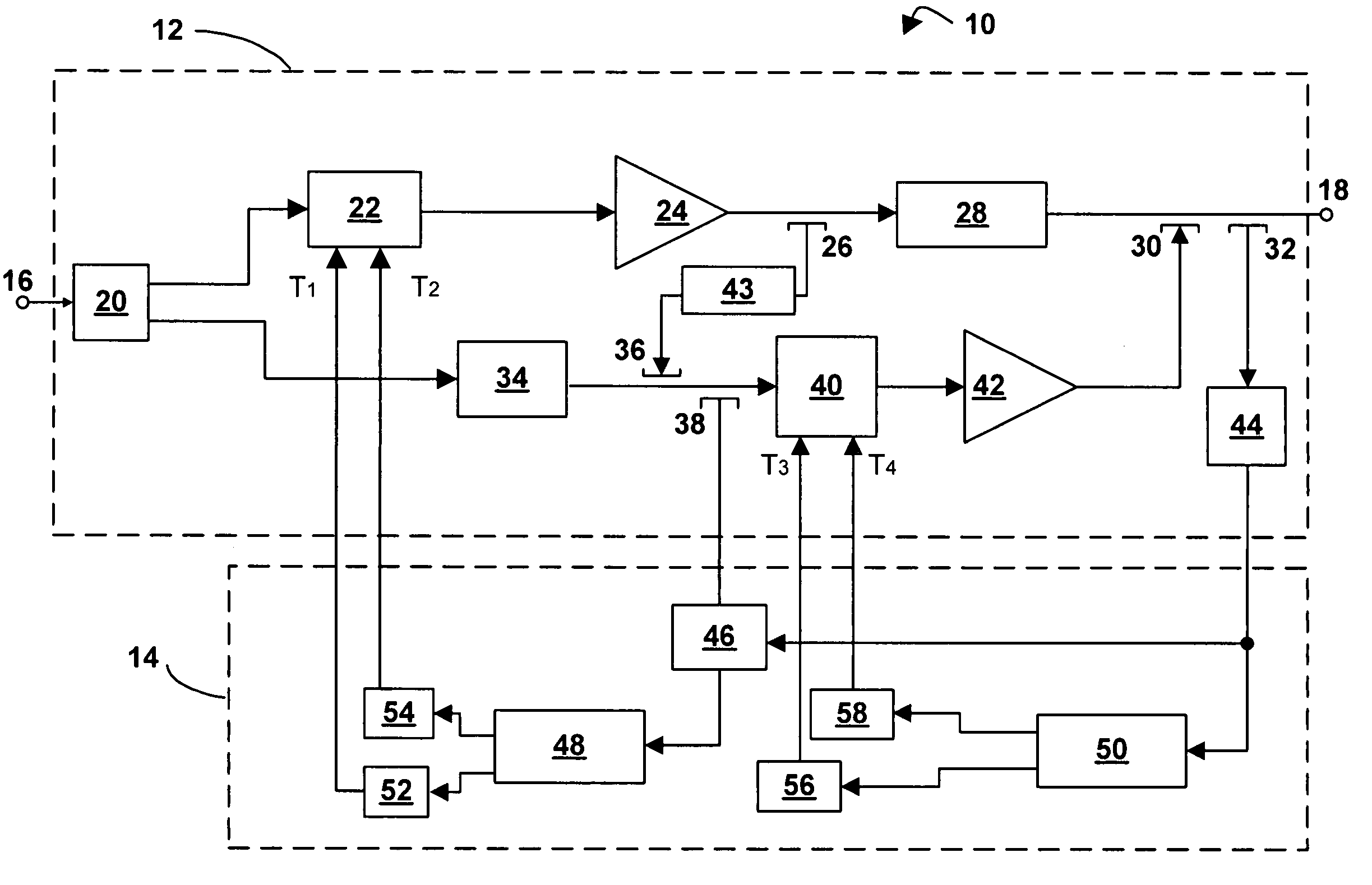
Figure 1 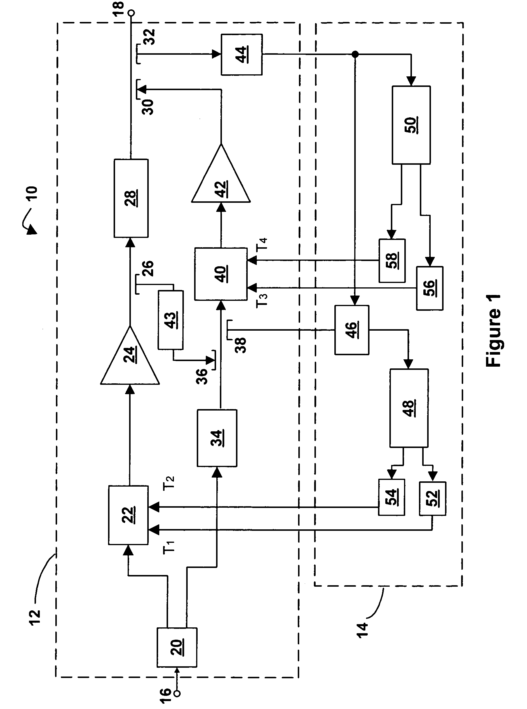
Figure 2
Abstract
Description
[0001] This application is a 371 of PCT / US03 / 19849, filed Jun. 25, 2003, which claims priority to US Provisional Application No. 60 / 391,084, filed Jun. 25, 2002, the entire contents of which is incorporated by reference herein.FIELD OF THE INVENTION
[0002] The present invention relates to feed-forward amplifiers. More specifically, the present invention relates to an apparatus and method for controlling gain and phase adjustments in a feed-forward amplifier.BACKGROUND OF THE INVENTION
[0003] One well-known form of amplifier is the feed-forward amplifier. In order to achieve linearity in a feed-forward amplifier, careful control of the amplifier circuitry is required. In particular, in feed-forward amplifiers two or more gain and phase adjusters are often employed and the taps of each of these adjusters are carefully steered to achieve linearity through the amplifier.
[0004] Within the art of feed-forward amplifiers, it is known to use detector-controller circuits, one for each gain-and-pha...
Examples
Embodiment Construction
[0020]Referring now to FIG. 1, a feed-forward amplifier in accordance with an embodiment of the invention is indicated generally by reference numeral 10. The feed-forward amplifier 10 comprises an amplifier portion 12 and a detector-controller portion 14.
[0021]The amplifier portion 12 has an input port 16 and an output port 18. A main signal path runs between the input port 16 and the output port 18 and consists of a series connection of a first main path splitter 20, a main signal path gain and phase adjuster 22, a main amplifier 24, a second main path splitter 26, a main signal path delay element 28, a first main path coupler 30, and a third main path splitter 32.
[0022]While one output of first main path splitter 20 continues along the main signal path, the other output of first main path splitter 20 heads along a feed-forward path consisting of a feed-forward signal path delay element 34, a feed-forward path coupler 36, a feed-forward path splitter 38, a feed-forward signal path ...