
Bar speed changing device
a technology of speed change and bar, which is applied in the direction of metal rolling, metal rolling stand, transportation and packaging, etc., can solve the problems of not being able to achieve the correct and repeatable bar unloading speed, excessive power consumption, and not being able to meet the specifications of the prior art with a 6 bar operating pressure, etc., and achieves considerable energy saving and less power.
Patent Information
- Authority / Receiving Office
- US · United States
- Patent Type
- Patents(United States)
- Current Assignee / Owner
- Publication Date
- 2009-07-14
Smart Images
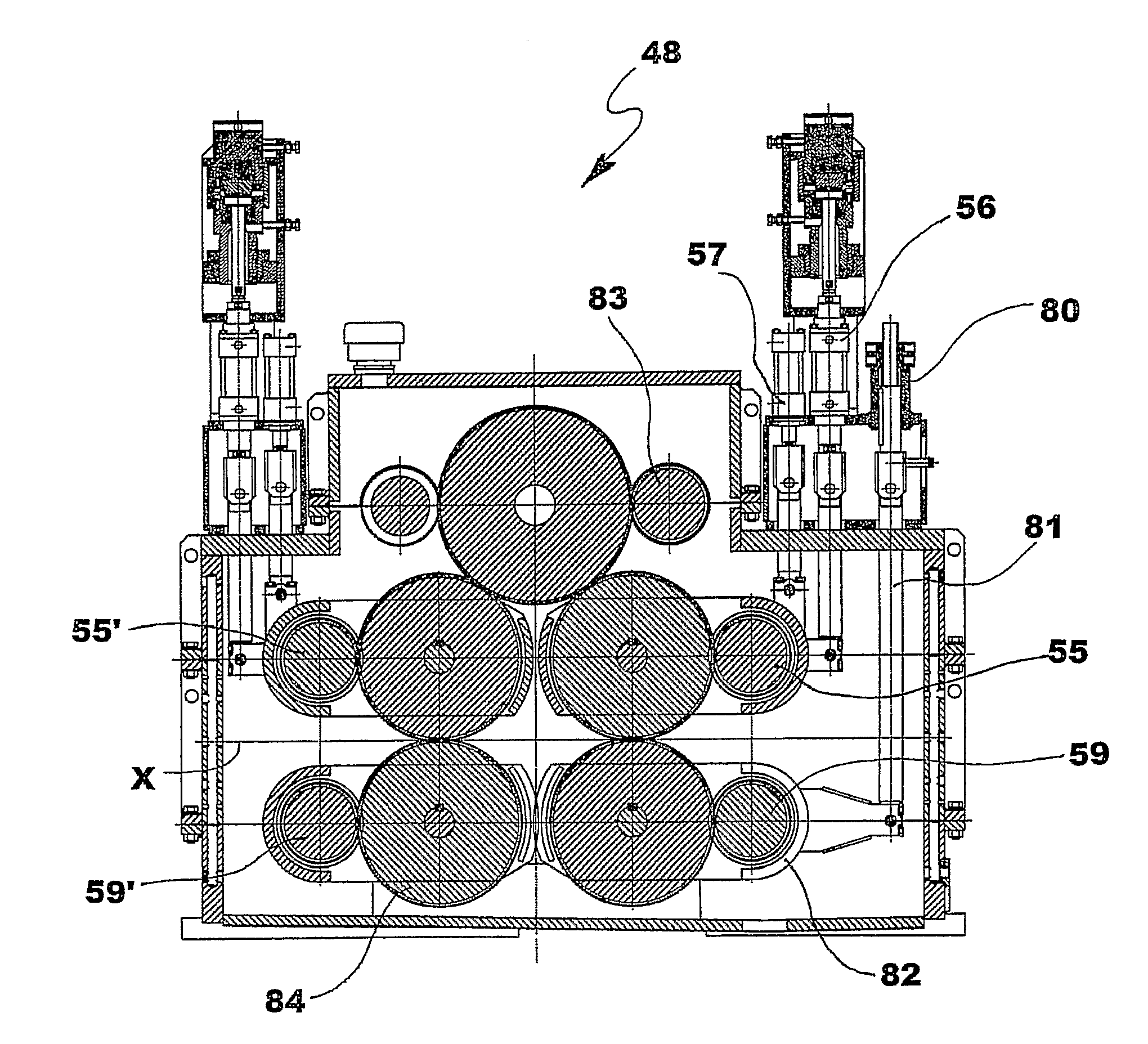
Figure 1 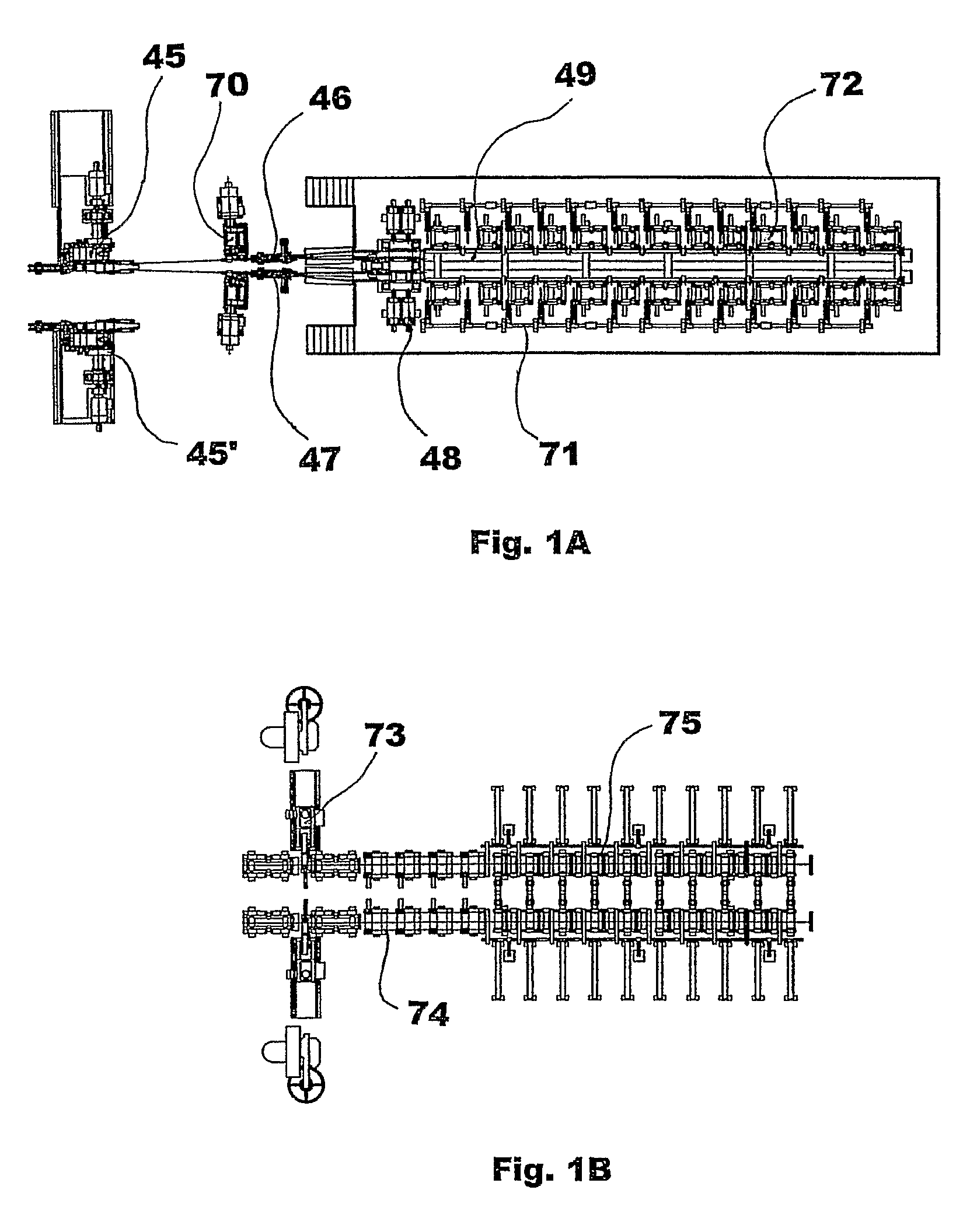
Figure 2 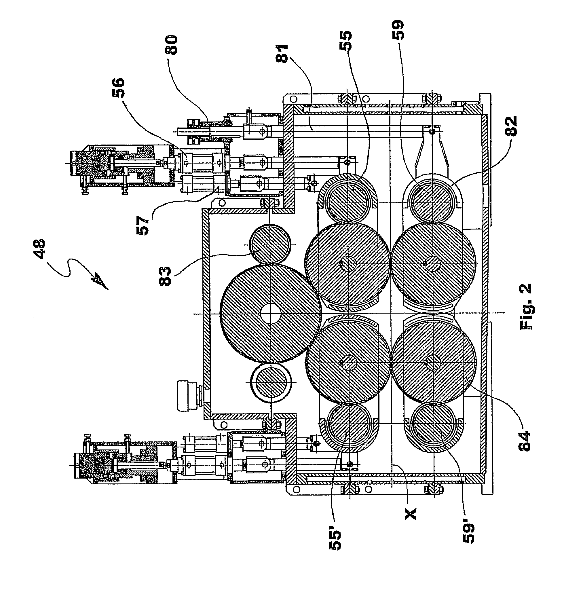
Figure 3
Abstract
Description
FIELD OF THE INVENTION
[0001] This invention relates to a bar speed changing device that can be used, for example, to change the speed of bars leaving a rolling mill.BACKGROUND OF THE INVENTION
[0002] A number of bar speed changing devices, more commonly referred to as bar braking devices, are known in the prior art. Said devices reduce the speed at which bars, that may have different cross-sections, are delivered. Said bars are rolled before being cut and packed.
[0003] The bar braking devices known in the prior art that are currently used operate as follows.
[0004] The bar braking device waits to receive the bar with the rollers open and rotating with a peripheral speed that is the same as the speed at which the bar is delivered. At a predefined moment, such to enable braking in the correct space and time, the rollers close on the bar and exert the braking action, exploiting the static friction between the roller-bar, since the peripheral speed of the roller is the same as the speed at wh...
Examples
Embodiment Construction
[0033]With reference to the drawings, a bar processing plant is now described. Said plant comprises:[0034]a cutting-to-length shearing machine 45 with integrated deflector device;[0035]two deflector devices 46 and 47 that divert the bars towards four unloading lines;[0036]a four-way bar braking assembly, comprising four bar speed changers 48. For the sake of simplicity, in the following description reference is only made to one of the two functions of the speed changer, namely to that in which it is used as a brake, and it is simply called a bar braking device. The term bar braking device thus also refers to the case in which the bars are made to accelerate;[0037]two twin-channel rotating assemblies 49, i.e. four rotating drum channels 50, 51, 52, 53;[0038]a device with one or more conveyors 60, 61, 62, 63 to unload the bar sections.
[0039]The cutting-to-length shearing machine 45 advantageously, but not necessarily, cuts the bars coming from a rolling mill, which is not illustrated ...