
Method and hydraulic control system for supplying pressure medium to at least one hydraulic consumer
Patent Information
- Authority / Receiving Office
- US · United States
- Current Assignee / Owner
- Publication Date
- 2013-08-06
- Estimated Expiration
- Not applicable · inactive patent
Smart Images
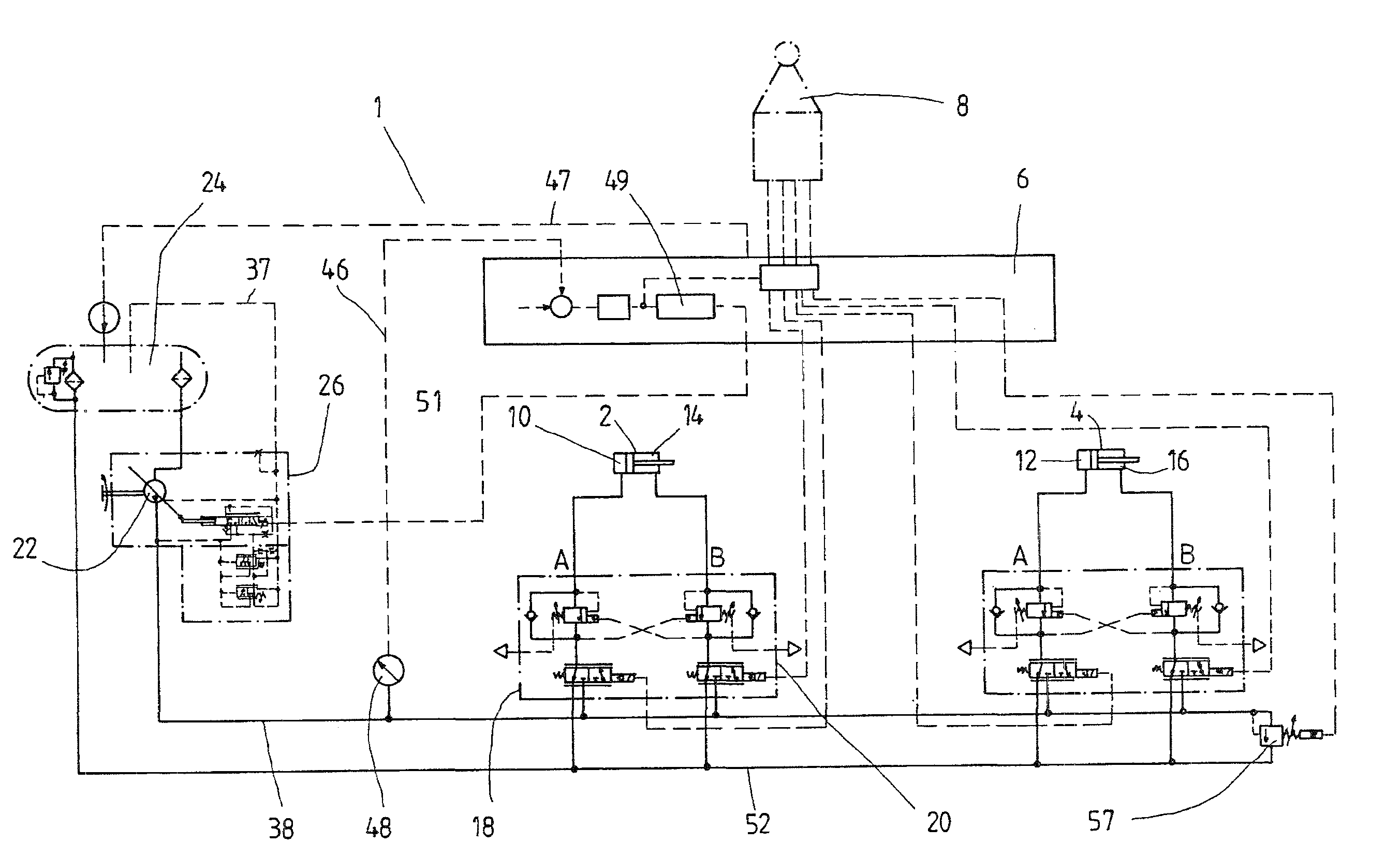
Figure 1 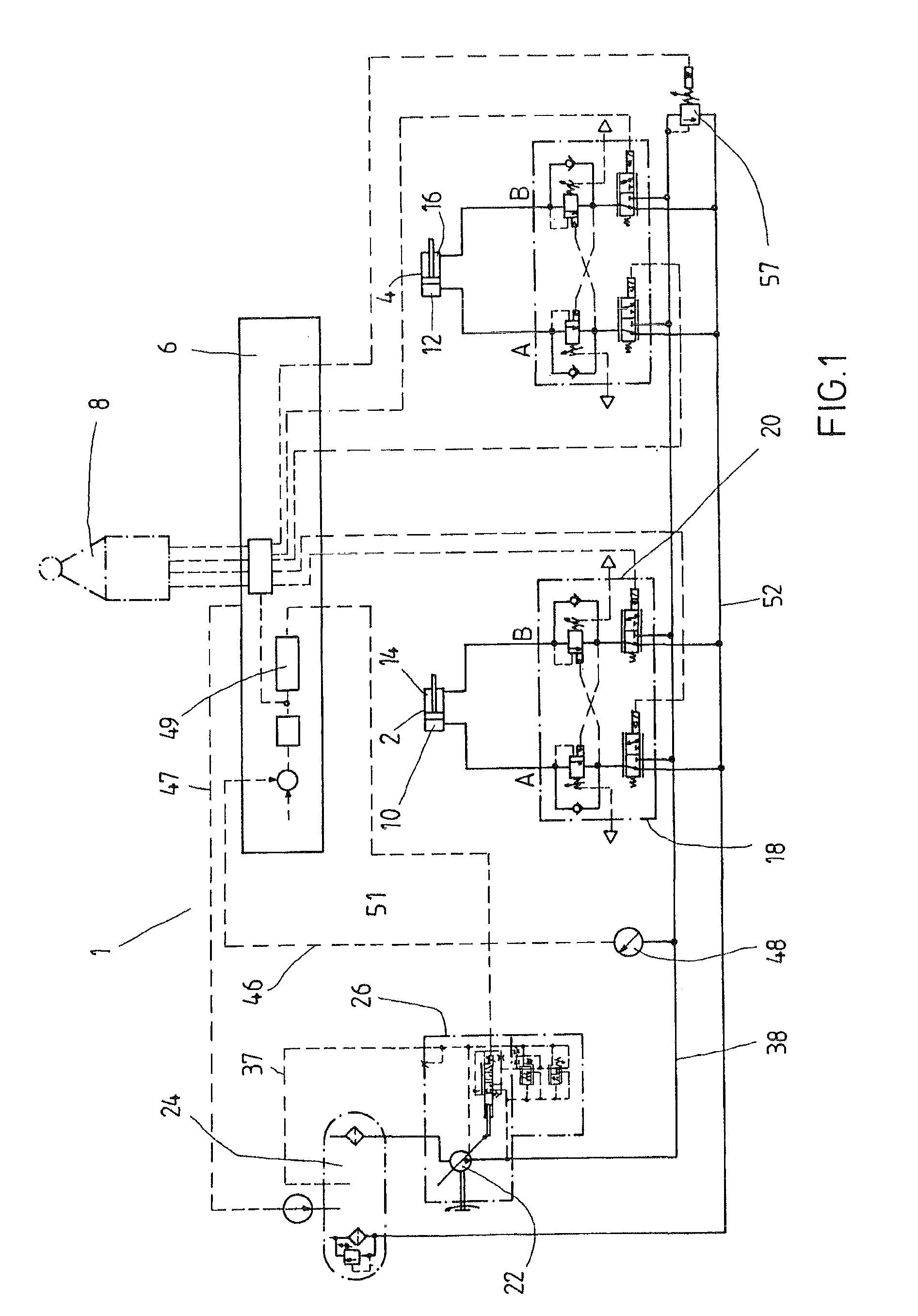
Figure 2 
Figure 3
Abstract
Description
CROSS-REFERENCE
[0001] The invention described and claimed hereinbelow is also described in PCT / EP2008 / 004990, filed on Jun. 20, 2008 and DE 10 2007 029 358.7, filed on Jun. 26, 2007. This German Patent Application, whose subject matter is incorporated here by reference, provides the basis for a claim of priority of invention under 35 U.S.C. 119 (a)-(d).BACKGROUND OF THE INVENTION
[0002] The invention relates to a method for actuating a hydraulic consumer and a hydraulic control system for supplying pressure medium to the consumer.
[0003] U.S. Pat. No. 5,138,883 A has disclosed a hydraulic control system in which a consumer such as a differential cylinder can be supplied via a valve device—which is equipped with two continuously adjustable directional control valves—with pressure fluid that is furnished by a pump. The supply to the consumer and the return from it each contain a respective continuously adjustable directional control valve. In their neutral positions, the directional contro...
Examples
Embodiment Construction
[0026]FIG. 1 shows a hydraulic control system 1 for supplying pressure fluid to two consumers 2, 4 of a piece of mobile equipment such as an excavator, a backhoe loader, a mini- or compact excavator, or a telehandler. It is a so-called
[0027]EFM system (electronic flow management) in which the valve elements that determine the volumetric flow of pressure fluid and the flow direction of the pressure fluid are electrically or electrohydraulically triggered as a function of characteristic curve families stored in a control unit 6. In this case, the setpoint values are input by means of a joystick 8 that is actuated by the operator in order to control the speed and position of the machine components (e.g. booms, shovels) of the piece of equipment.
[0028]In the exemplary embodiment shown, the two consumers 2, 4 are each embodied in the form of a differential cylinder with a pressure chamber 10 or 12 at the bottom and an annular chamber 14 or 16 around the piston rod. These pressure chamber...