
Hard disk drive DSA suspension having PZT encapsulation dam
a suspension and hard disk technology, applied in the direction of magnetic recording, data recording, instruments, etc., can solve the problems of scratches on the surface, small particles of pzt crystals, etc., and achieve the effect of not unduly reducing the stroke length of the pzt microactuator and sufficient flexibility of the suspension structur
Patent Information
- Authority / Receiving Office
- US · United States
- Patent Type
- Patents(United States)
- Current Assignee / Owner
- Publication Date
- 2013-09-03
Smart Images
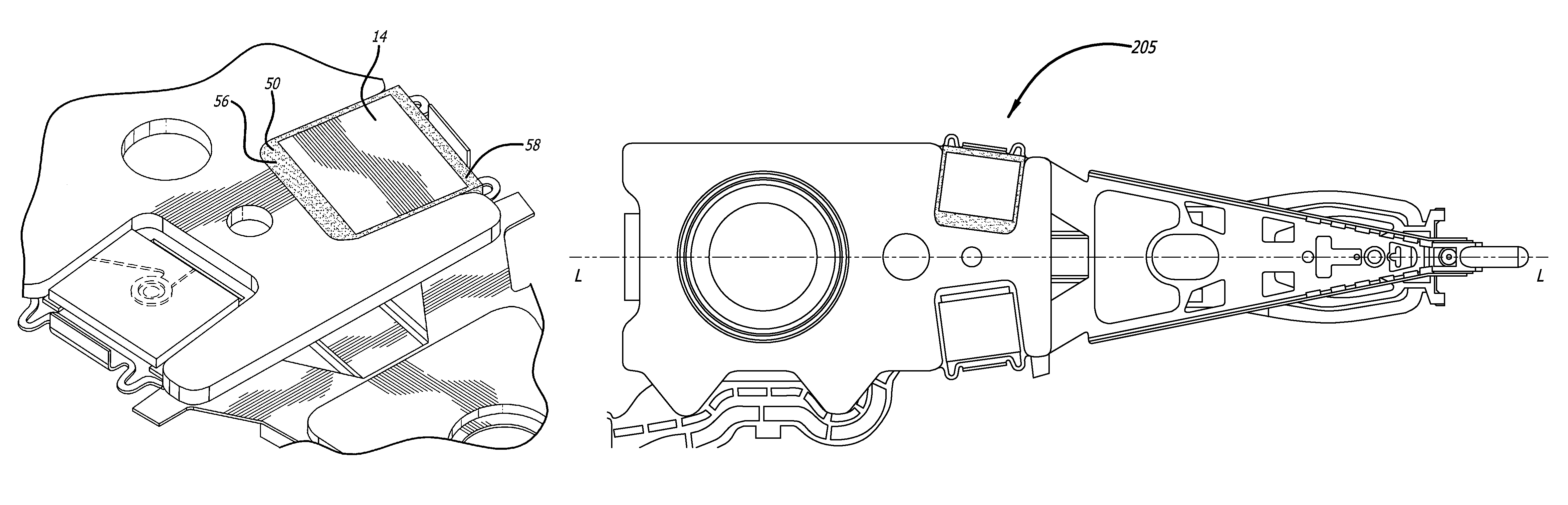
Figure 1 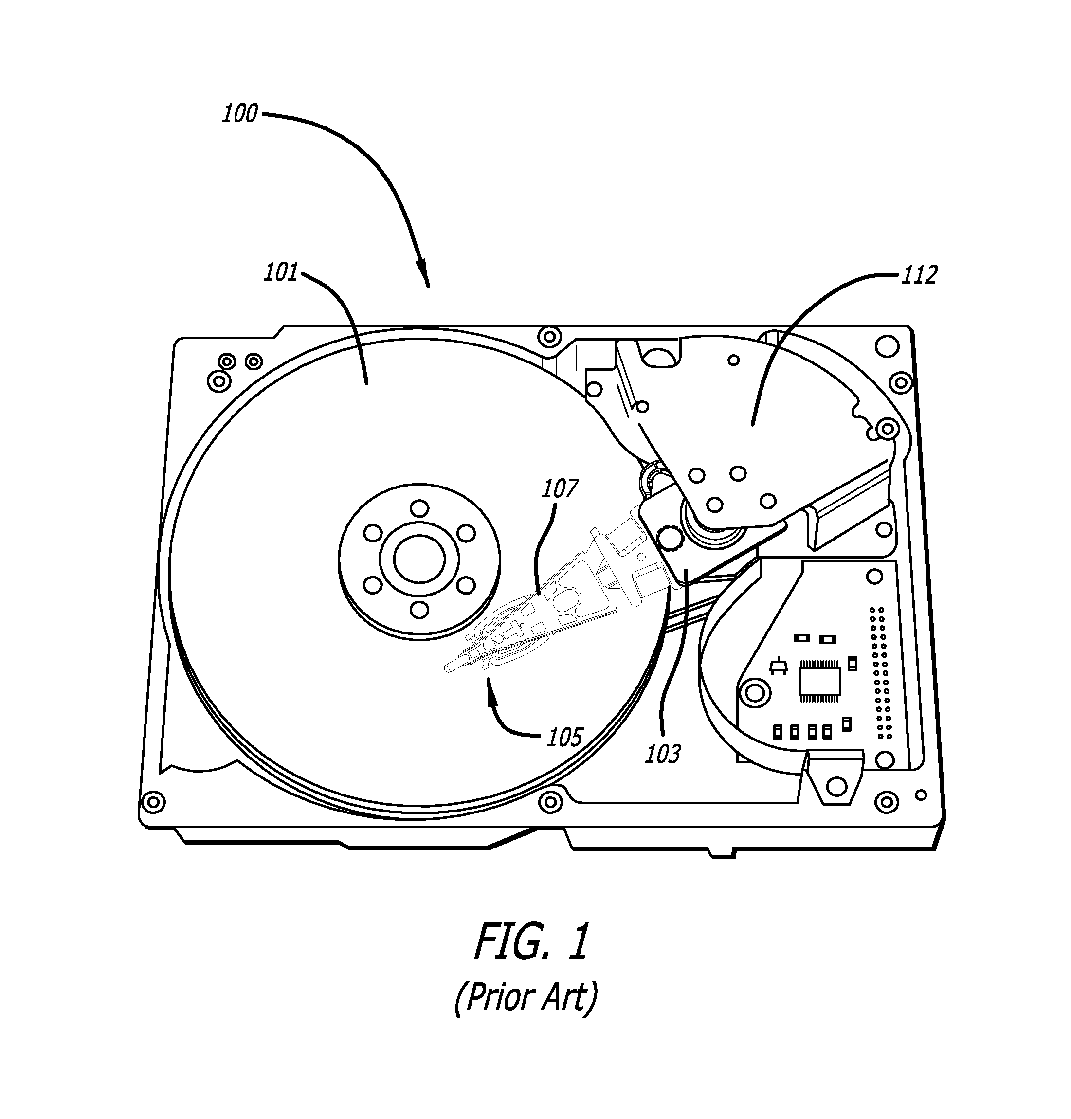
Figure 2 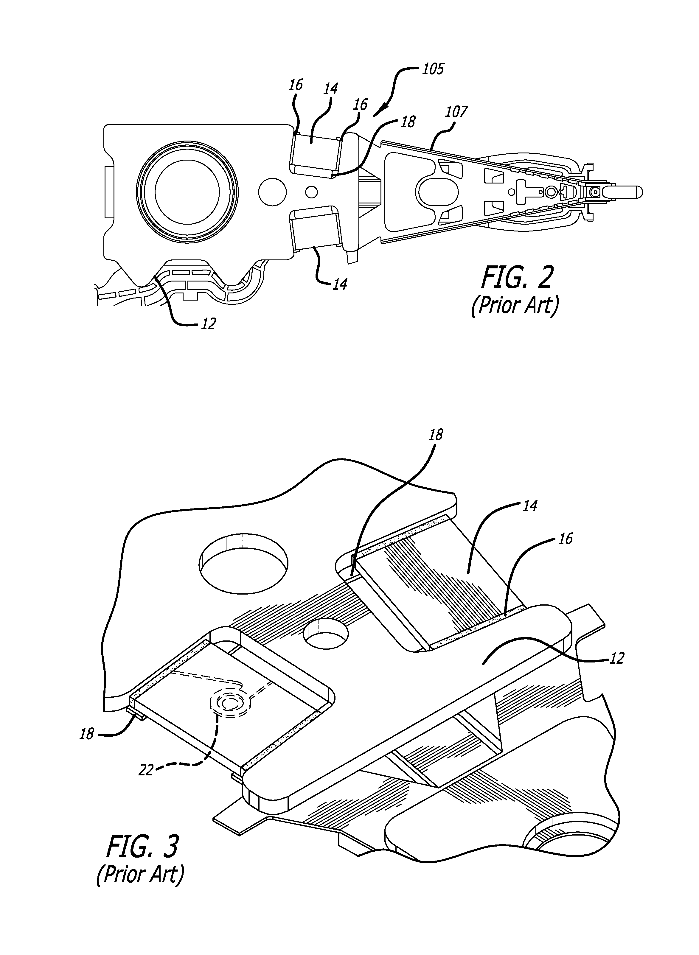
Figure 3
Abstract
Description
CROSS-REFERENCE TO RELATED APPLICATIONS
[0001] This application claims priority from U.S. Provisional Patent Application Ser. No. 61 / 428,829 filed Dec. 30, 2010.BACKGROUND OF THE INVENTION
[0002] 1. Field of the Invention
[0003] This invention relates to the field of suspensions for disk drives. More particularly, this invention relates to the field of a hard disk drive (HDD), dual stage actuation (DSA) suspension having a PZT encapsulation dam formed in the suspension.
[0004] 2. Description of Related Art
[0005] Magnetic hard disk drives and other types of spinning media drives such as optical disk drives are well known. FIG. 1 is an oblique view of an exemplary prior art hard disk drive and suspension for which the present invention is applicable. The prior art disk drive unit 100 includes a spinning magnetic disk 101 containing a pattern of magnetic ones and zeroes on it that constitutes the data stored on the disk drive. The magnetic disk is driven by a drive motor (not shown). Disk drive...
Examples
Embodiment Construction
[0025]FIG. 5 is an oblique view of a suspension 205 according to a first embodiment of the invention, and FIG. 6 is a top plan closeup view thereof. Suspension body portion 20, which in the illustrative embodiment is base plate 12 but alternatively could also be a different part of the suspension such as the load beam, includes a pair of integrally formed wing rails 30 outward of the PZTs that help to contain a non-conductive adhesive (not shown in these figures) such as epoxy, and thus serve as adhesive containment rails. The epoxy is preferably at least somewhat elastic. Although other shapes are possible, in the embodiment shown the adhesive containment rails 30 include substantially horizontal and substantially flat sections 34, bent or upturned sides 32, and relief features or resilient features 36 such as C-shaped or S-shaped springs, or other shape containing one or more curved section such as serpentine shaped sections. In the preferred embodiment, containment rail 30 is for...