
Sub-motor-threshold stimulation of deep brain targets using transcranial magnetic stimulation
a transcranial magnetic stimulation and sub-motor technology, applied in magnetotherapy, magnetotherapy using coils/electromagnets, magnetotherapy, etc., can solve the problems of unexpective effective sub-mt stimulation and achieve the effect of easier fire and greater probability of excitation
Patent Information
- Authority / Receiving Office
- US · United States
- Patent Type
- Patents(United States)
- Current Assignee / Owner
- Publication Date
- 2014-08-05
Smart Images
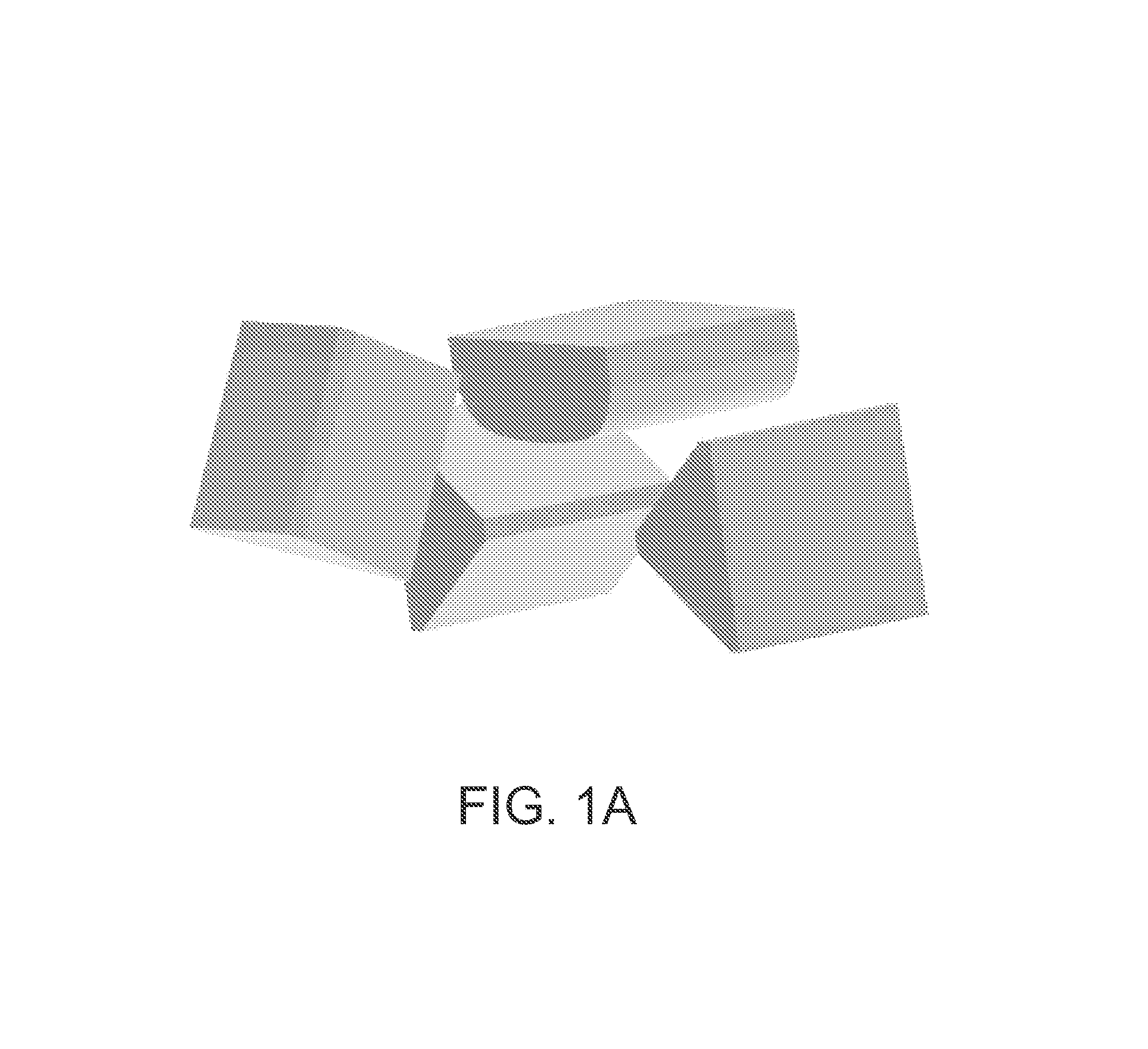
Figure 1 
Figure 2 
Figure 3
Abstract
Description
CROSS REFERENCE TO RELATED APPLICATIONS
[0001] This patent application claims priority to provisional patent application Ser. No. 61 / 254,964, filed on Oct. 26, 2009, titled “SUB-MOTOR-THRESHOLD STIMULATION OF DEEP BRAIN TARGETS USING TRANSCRANIAL MAGNETIC STIMULATION,” which is herein incorporated by reference in its entirety.
[0002] This patent application may be related to pending PCT application PCT / 2008 / 073751, filed on Aug. 20, 2008, which claims priority to U.S. Provisional Patent Application Ser. No. 60 / 956,920, filed on Aug. 20, 2007, U.S. Provisional Patent Application Ser. No. 60 / 970,958, filed on Sep. 9, 2007, and U.S. Provisional Patent Application Ser. No. 61 / 077,488, filed on Jul. 2, 2008. This patent application may also be related to PCT application PCT / US2008 / 075575 (WO 2009 / 033144), filed on Sep. 8, 2008, which claims priority to U.S. Provisional Patent Application Ser. Nos. 60 / 970,534, filed Sep. 7, 2007; 60 / 970,532, filed Sep. 7, 2007; and 60 / 975,177, filed Sep. 26, ...
Examples
Embodiment Construction
[0023]One variation of an experimental set-up is illustrated in FIG. 1A. FIG. 1A illustrates a TMS system including four TMS electromagnets. In FIG. 1A, the CAD model illustrates an arrangement of magnets which may be referred to as a “diamond array.” The subject's head and any electromagnet coil fixation device are not shown in this figure. These four TMS electromagnets may be connected to a scaffold, gantry, or other fixation device. In FIG. 1A, the center, top TMS electromagnet is a swept-wing coil and the two lateral coils are V-Coils in the same vertical plane. A third V-Coil is located anteriorly, swinging down and configured to touch the subject's forehead.
[0024]FIGS. 1B to 1C illustrate a system such as the one shown in FIG. 1A. For example, FIG. 1B shows a front view of such a system and FIG. 1C shows a side view. FIG. 1D shows a diamond-array configuration of a TMS system relative to standard EEG placement landmarks. The centers of the electromagnets are located at the lan...