
Coupler knuckle
a technology of couplers and knuckles, which is applied in the direction of railway couplings, railway coupling accessories, railway components, etc., can solve the problems of coupler-knuckle assembly design that does not consistently meet, damage or break the pin or assembly, and the coupler-knuckle assembly is not consistent, so as to prevent bending and breakage of the knuckle pin. , the effect of reducing fatigu
Patent Information
- Authority / Receiving Office
- US · United States
- Patent Type
- Patents(United States)
- Current Assignee / Owner
- Publication Date
- 2014-12-16
Smart Images
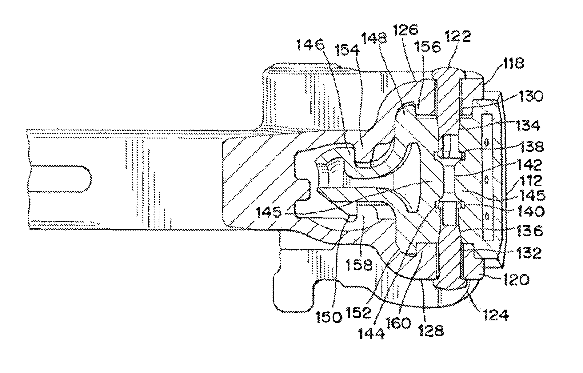
Figure 1 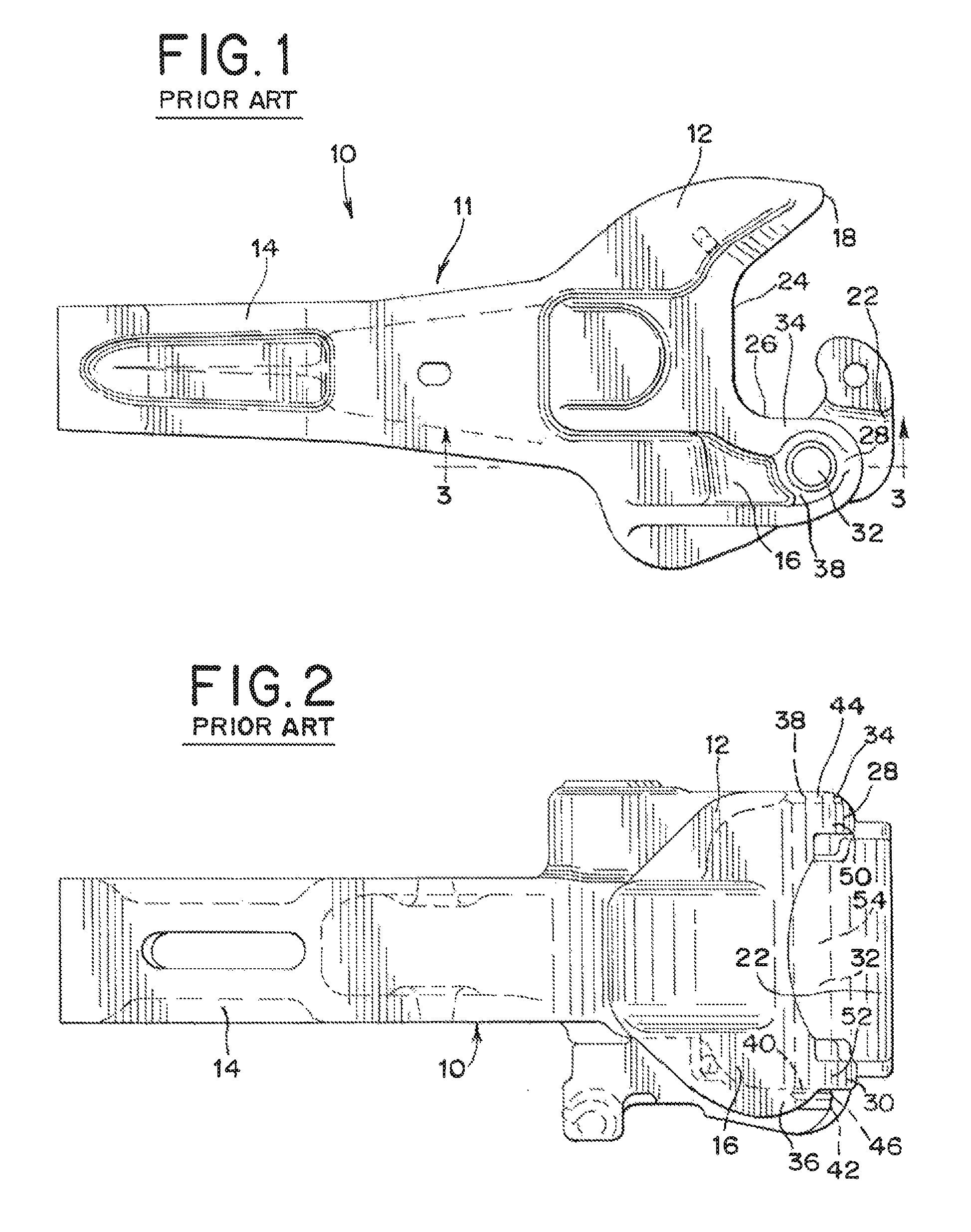
Figure 2 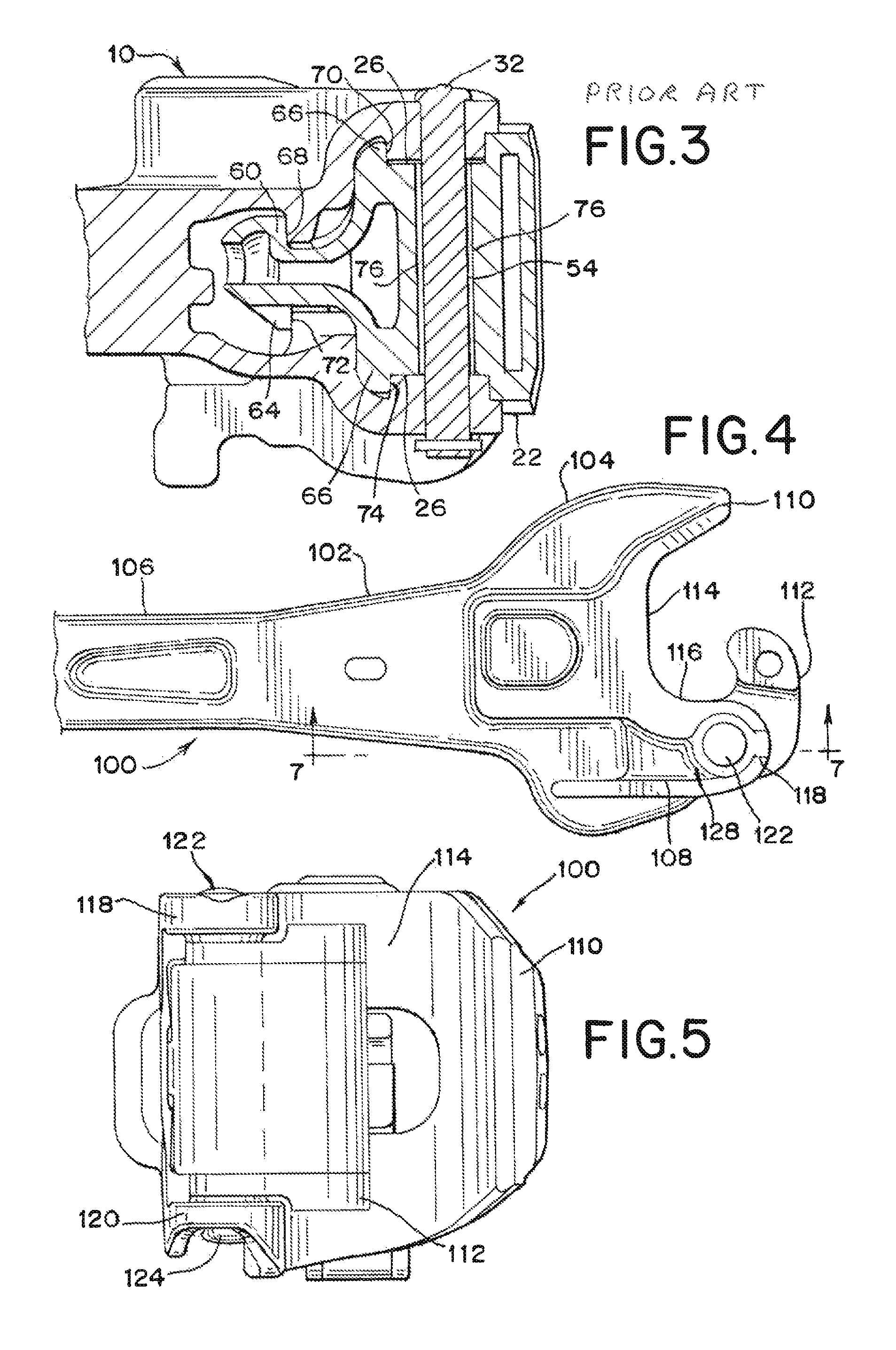
Figure 3
Abstract
Description
BACKGROUND OF THE INVENTION
[0001] The invention relates generally to railway car coupling systems, and more particularly to an improved cast metal coupler-knuckle assembly.
[0002] This invention is applicable to Association of American Railroads (AAR) Type E, F, and H couplers. In a standard railway coupler-knuckle assembly, a knuckle pin pivotally connects a coupler body and a knuckle. Both the coupler body and the knuckle have a pinhole that allows a single knuckle pin to pivotally secure the coupler and the knuckle together.
[0003] In the coupler-knuckle assembly design that is currently used in the railway industry, the knuckle's weakest section is in the throat area around the hole for the knuckle pin. The hole is 1 21 / 32 inches in diameter and goes completely through the coupler and the knuckle. The pinhole reduces the cross-section area of the knuckle's throat area, which is a highly stressed location in the coupler-knuckle assembly. Because of this weakness in the throat area of ...
Examples
Embodiment Construction
[0026]Referring now to FIGS. 1-3, an E-type coupler-knuckle assembly known in the prior art is generally designated 10 and includes a coupler body 11, a knuckle 22, and a knuckle pin 32. The coupler body 11 comprises generally a coupler head 12 and a coupler shank 14 which is adapted to be mounted on a railway car (not shown). The coupler-knuckle assembly 10 serves to transfer buff and draft loads that are exerted on the assembly 10 during use, from the knuckle 22 to the coupler body 11, without damaging knuckle pin 32.
[0027]The coupler head 12 has a knuckle side 16 and a guard arm side 18. Coupler head 12 has a front face 24 including a throat portion 26 extending towards the knuckle side 16 in a curved manner toward upper pivot lug 28 and lower pivot lug 30. Coupler head 12 includes outwardly protruding flange sections 34 and 36 from the top surface 38 of upper pivot lug 28 and the bottom surface 64 of lower pivot lug 30 respectively. Along with pulling and buffing loads on a coup...