
Method of determining the position and the speed of a rotor in a synchronous electric machine using state observers
a synchronous electric machine and state observer technology, applied in the field of control of synchronous electric machines, can solve the problems of low-cost position detectors that are not accurate enough, detectors can be subject to failure, and cannot accurately control the torque of electric machines, etc., and achieve accurate position information and robust rejection of measurement noise.
Patent Information
- Authority / Receiving Office
- US · United States
- Patent Type
- Patents(United States)
- Current Assignee / Owner
- Publication Date
- 2016-09-13
Smart Images
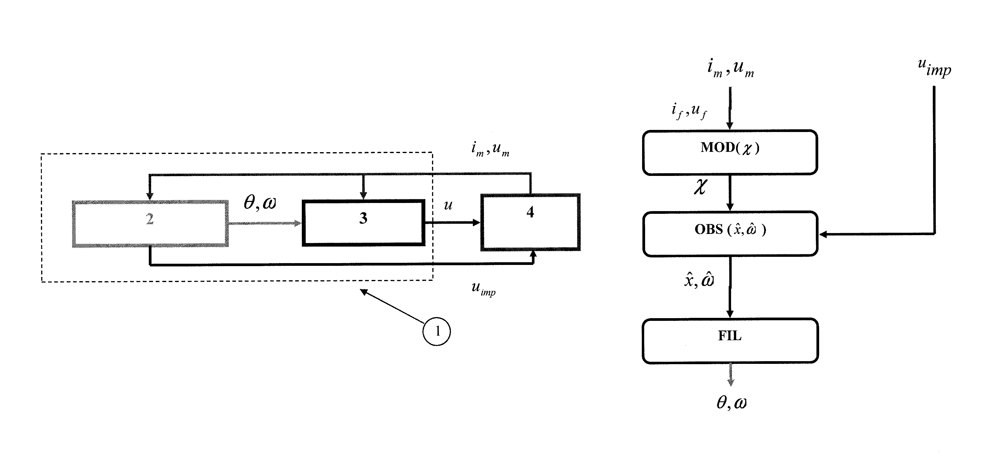
Figure 1 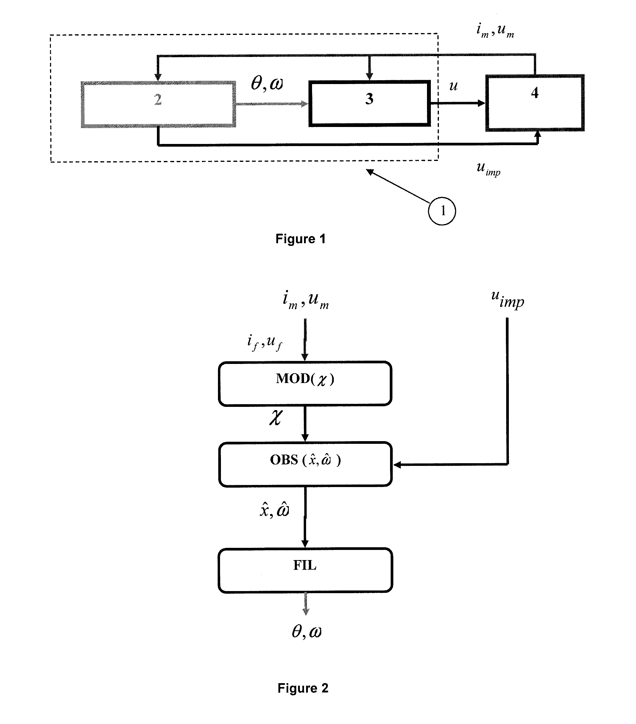
Figure 2 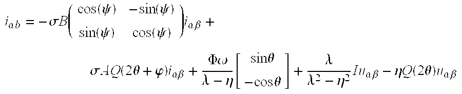
Figure 3
Abstract
Description
CROSS REFERENCE TO RELATED APPLICATION
[0001] Reference is made to French Patent Application Serial No. 13 / 54.520, filed May 21, 2013, which application is incorporated herein by reference in its entirety.BACKGROUND OF THE INVENTION
[0002] 1. Field of the Invention
[0003] The present invention relates to the control of synchronous electric machines, notably for motor vehicles.
[0004] 2. Description of the Prior Art
[0005] A synchronous machine is comprised of a rotating part which is the rotor and of a stationary part which is the stator. The rotor can be made up of permanent magnets or of a DC-powered coil and a magnetic circuit which is referred to as the electromagnet. The stator comprises three phases with each phase having at least one coil (also referred to as winding) connected thereto with the coils being supplied with electrical power and voltage. An external force is used to rotate the rotor which is a magnetic field induced by an alternating electric current in the coils (windings)...
Examples
Embodiment Construction
[0046]It is to be noted that the method and the system according to the invention are suited for salient-pole synchronous electric machines. The synchronous electric machine can be either one of using a permanent magnet for providing, controlled excitation or using double excitation. Such a machine is comprised of a rotating part which is the rotor and of a stationary part which is the stator. The rotating part comprises at least one magnet (or electromagnet). The stator comprises at least three coils distributed among three phases, which are supplied electrical current alternately to generate a magnetic field which rotates the rotor. The coils are supported by a frame referred to as the casing.
[0047]FIG. 1 illustrates the control of a synchronous electric machine conventionally made up of three phases. Electric machine (4) is provided with means for measuring the phase voltages and currents; which are well known and not shown. Control means (1) of the electric machine include means...