
Image pickup apparatus, image pickup system, signal processing apparatus, and non-transitory computer-readable storage medium
a technology of image pickup and signal processing, which is applied in the field of image pickup apparatus, can solve the problems of deteriorating focus detection accuracy in the periphery of the screen, and achieve the effect of avoiding influence and high-accurate focus detection
Patent Information
- Authority / Receiving Office
- US · United States
- Patent Type
- Patents(United States)
- Current Assignee / Owner
- Publication Date
- 2016-09-13
Smart Images
Figure 1 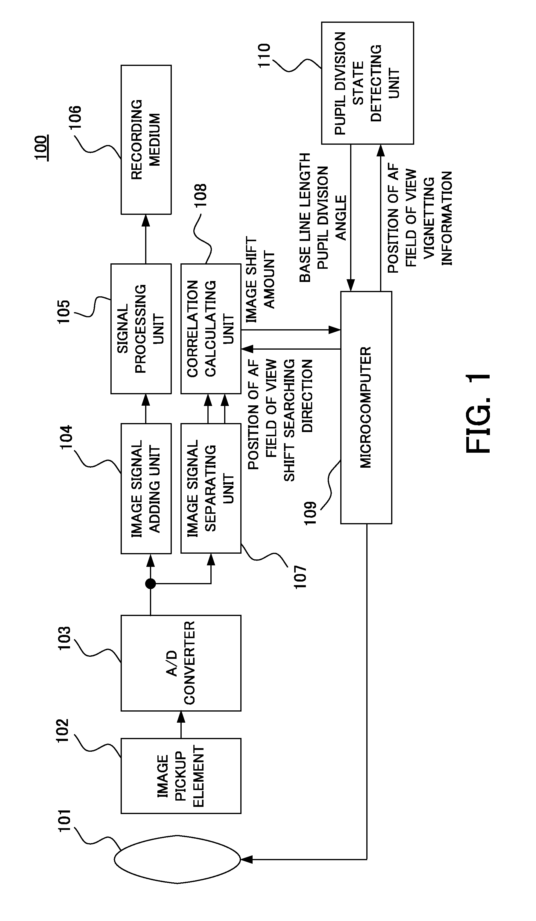
Figure 2 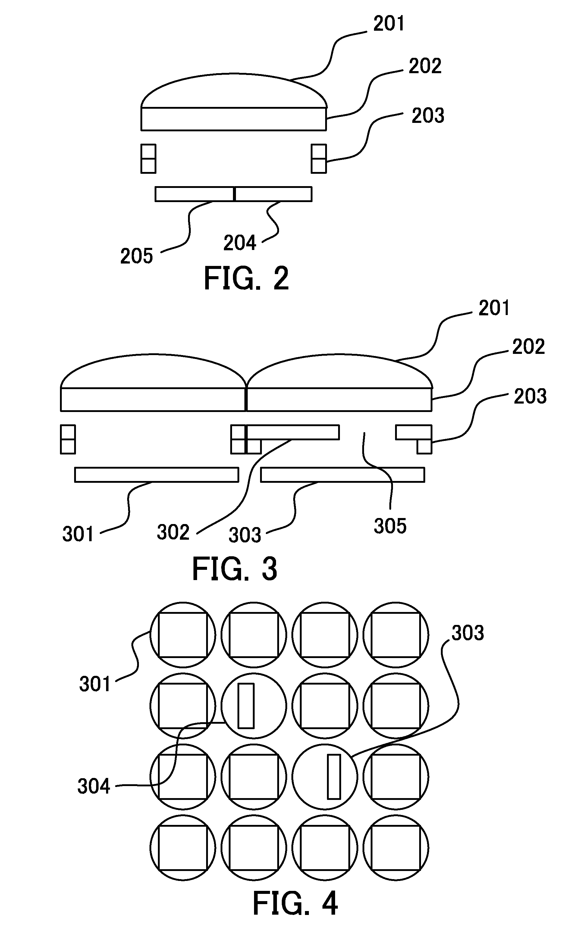
Figure 3
Abstract
Description
BACKGROUND OF THE INVENTION
[0001] 1. Field of the Invention
[0002] The present invention relates to an image pickup apparatus which performs focus detection using light beams passing through pupil regions different from each other in an image pickup optical system.
[0003] 2. Description of the Related Art
[0004] Previously, a focus detection method of using a phase difference detection method has been known. In the phase difference detection method, a light beam passing through an exit pupil of a lens is divided, and the divided light beams are received by a pair of focus detection sensors. Then, a drive amount of the lens required to achieve an in-focus state is obtained based on a shift amount of signals outputted depending on light receiving amounts of the divided light beams, i.e. a relative position shift amount of the light beams in a division direction. Accordingly, since an amount and direction of defocus is obtained when an accumulation is performed once by the focus detection sen...
Examples
embodiment 1
[0041]First of all, referring to FIG. 1, a defocus detection apparatus (an image pickup apparatus) will be described. FIG. 1 is a block diagram of an image pickup apparatus 100 in the present embodiment. In the image pickup apparatus 100, reference numeral 101 denotes a lens unit (an image pickup optical system) including a focus lens or an aperture stop mechanism. In the present embodiment, the image pickup apparatus 100 (an image pickup apparatus body) is configured integrally with the lens unit 101, but the embodiment is not limited to this. The present embodiment can also be applied to an image pickup system that is configured by the image pickup apparatus body and a lens unit removably mounted on the image pickup apparatus body.
[0042]Reference numeral 102 denotes an image pickup element (an image signal generating unit) that has a structure of a pixel illustrated for example in FIG. 2, which photoelectrically converts an object image (an optical image) obtained via an image pic...
embodiment 2
[0061]Next, a defocus detection apparatus (an image pickup apparatus) in Embodiment 2 of the present invention will be described. First of all, referring to FIG. 3, a structure of pixels of an image pickup element in the present embodiment will be described. FIG. 3 is a cross-sectional view of the pixels of the image pickup element in the present embodiment. Reference numeral 201 denotes a microlens, reference numeral 202 denotes a color filter, and reference numeral 203 denotes a wiring layer. Reference numeral 301 denotes a pixel (an image pickup pixel) which is used to generate a normal image signal. Reference numeral 303 denotes a pixel (a focus detection pixel) which is used to generate a focus detection signal. Reference numeral 302 denotes a light blocking portion which extends the wiring layer 203 to an upper portion of the pixel to block the light. With respect to the pixel 303 illustrated in FIG. 3, light enters the pixel 303 only through an opening portion 305 at the righ...