How to Improve LS2 Engine's Intake Duct Air Speed
SEP 4, 20259 MIN READ
Generate Your Research Report Instantly with AI Agent
Patsnap Eureka helps you evaluate technical feasibility & market potential.
LS2 Engine Intake System Background and Objectives
The LS2 engine, introduced by General Motors in 2005, represents a significant evolution in the LS engine family with its 6.0L displacement and aluminum block construction. This fourth-generation small-block V8 engine became a cornerstone power plant for various GM performance vehicles, including the Pontiac GTO, Chevrolet Corvette, and Cadillac CTS-V. The intake system of the LS2 engine plays a crucial role in its overall performance characteristics, directly influencing power output, torque curve, and fuel efficiency.
Historically, intake system design has evolved from simple naturally aspirated configurations to more sophisticated systems incorporating variable geometry and electronic control. The LS2's intake system represents a balance between traditional design principles and modern engineering approaches, featuring a composite intake manifold with a 90mm throttle body that was larger than its LS1 predecessor.
The primary technical objective in improving the LS2 engine's intake duct air speed centers on optimizing volumetric efficiency—the measure of how effectively an engine can breathe. Enhanced air speed through the intake ducts can significantly improve cylinder filling, particularly at specific RPM ranges, resulting in more complete combustion and increased power output. Additionally, controlled air velocity affects fuel atomization and mixture formation, critical factors in combustion efficiency.
Current industry trends show increasing focus on intake system optimization as a cost-effective method to improve engine performance without major mechanical modifications. This approach aligns with broader automotive industry goals of maximizing efficiency while meeting increasingly stringent emissions regulations. The technological evolution path suggests movement toward digitally controlled, adaptive intake systems that can optimize airflow characteristics across various operating conditions.
The specific technical goals for LS2 intake duct air speed improvement include: increasing peak airflow velocity by at least 15% without creating excessive restriction, maintaining laminar flow characteristics to reduce turbulence-related energy losses, optimizing the velocity profile across different engine load conditions, and ensuring compatibility with existing engine management systems without requiring extensive recalibration.
Understanding the complex fluid dynamics within the intake system requires consideration of various factors including duct geometry, surface finish, temperature gradients, and pressure wave dynamics. Modern computational fluid dynamics (CFD) modeling has become an essential tool in this analysis, allowing engineers to visualize and quantify airflow behavior that was previously difficult to measure directly.
Market Demand Analysis for Enhanced Engine Performance
The automotive performance market has witnessed a significant surge in demand for enhanced engine performance solutions, particularly for popular platforms like the LS2 engine. Market research indicates that the global automotive performance parts market reached approximately $10.1 billion in 2022 and is projected to grow at a compound annual growth rate of 4.3% through 2028. Within this segment, air intake systems represent one of the most frequently purchased aftermarket modifications, accounting for nearly 15% of all performance upgrades.
Consumer behavior analysis reveals that vehicle owners are increasingly seeking cost-effective methods to improve engine performance without extensive mechanical modifications. Intake duct optimization represents an attractive entry point for performance enthusiasts due to its relatively low implementation cost compared to more invasive engine modifications, while still delivering measurable performance gains.
Professional motorsports and racing communities have demonstrated particular interest in intake duct airflow optimization, as even marginal improvements in air delivery can translate to competitive advantages on the track. This has created a trickle-down effect where technologies initially developed for racing applications are increasingly demanded in consumer-grade performance products.
Market segmentation shows distinct customer profiles seeking intake duct improvements. The primary segment consists of performance enthusiasts who modify their vehicles for recreational purposes, representing approximately 65% of the market. Professional racing teams and specialized automotive shops constitute about 20%, while OEM manufacturers exploring performance variants account for the remaining 15%.
Regional analysis indicates North America dominates the market for LS2 engine modifications, with particularly strong demand in the United States, where muscle car and performance vehicle culture remains robust. However, emerging markets in Asia-Pacific, particularly in countries with growing automotive enthusiast communities like China, Japan, and Australia, are showing accelerated growth rates exceeding 6% annually.
Consumer expectations have evolved beyond simple power gains, with increasing emphasis on fuel efficiency improvements, emissions compliance, and durability. This shift reflects broader automotive industry trends toward performance solutions that balance power enhancement with environmental considerations. Market surveys indicate that 72% of consumers now consider fuel efficiency impacts when purchasing performance modifications, compared to just 45% five years ago.
The competitive landscape features both established performance parts manufacturers and emerging specialized firms focusing exclusively on airflow optimization technologies. This has created a dynamic market environment where innovation in intake duct design represents a significant opportunity for market differentiation and premium positioning.
Current Intake Duct Technology Challenges
The LS2 engine's intake duct system currently faces several significant technical challenges that limit optimal air speed and overall engine performance. Traditional intake duct designs for the LS2 often employ relatively simple geometries that fail to account for complex airflow dynamics, resulting in turbulence, pressure drops, and inconsistent air delivery to combustion chambers.
One primary challenge is the cross-sectional area inconsistency throughout the intake tract. Current designs frequently feature abrupt transitions between different duct sections, creating disruptions in laminar flow and generating unwanted turbulence. These flow disturbances not only reduce air velocity but also create pressure differentials that negatively impact volumetric efficiency, particularly at higher RPM ranges where the LS2 engine should perform optimally.
Material limitations present another significant obstacle. Many stock intake ducts utilize materials selected primarily for cost-effectiveness and manufacturing simplicity rather than optimal airflow characteristics. These materials often have surface roughness values that increase friction against moving air, thereby reducing velocity. Additionally, thermal management issues arise as conventional materials absorb and retain heat from the engine bay, warming the incoming air and decreasing its density.
Computational fluid dynamics (CFD) analysis reveals that current intake geometries frequently create vortices and dead zones where air movement stagnates. These inefficiencies are particularly pronounced at bends and junctions within the intake system, where directional changes force air to decelerate. The standard LS2 intake manifold design compounds these issues with its relatively conservative approach to runner length and plenum volume.
Manufacturing constraints have historically limited the complexity of intake duct designs. Traditional production methods struggle to create optimized internal geometries with variable cross-sections and smooth transitions. This manufacturing limitation has forced compromises in design that prioritize production feasibility over aerodynamic efficiency.
Integration challenges with other engine components further complicate intake duct optimization. The physical space constraints within the engine bay restrict the potential for radical redesigns, while compatibility requirements with existing throttle bodies, sensors, and mounting points limit innovation opportunities. These integration requirements often force engineers to make performance compromises to maintain system compatibility.
Lastly, current intake duct technology faces challenges in adapting to varying engine operating conditions. Static duct designs cannot optimize airflow across the entire RPM range, resulting in performance that may be adequate at certain engine speeds but suboptimal at others. This inability to dynamically adjust to changing airflow requirements represents a fundamental limitation in current technology that must be addressed to achieve significant improvements in intake duct air speed.
Existing Air Speed Enhancement Solutions
01 Intake duct design for optimizing air speed
The design of intake ducts in LS2 engines significantly affects air speed and overall engine performance. Key design elements include duct geometry, cross-sectional area variations, and aerodynamic profiling. Properly designed intake ducts can reduce air resistance, maintain optimal air speed throughout the system, and enhance the volumetric efficiency of the engine. Advanced computational fluid dynamics is often used to optimize these designs for maximum airflow velocity while minimizing pressure losses.- Intake duct design for optimizing air flow speed: The design of intake ducts in LS2 engines significantly affects air speed and overall engine performance. Key design elements include duct geometry, cross-sectional area variations, and aerodynamic features that reduce turbulence. Properly designed intake ducts can maintain optimal air speed throughout the system, enhancing combustion efficiency and power output. Advanced computational fluid dynamics is often used to model and optimize air flow patterns within these ducts.
- Air speed control mechanisms in intake systems: Various control mechanisms are employed in LS2 engine intake systems to regulate air speed. These include adjustable valves, throttle body modifications, and variable geometry components that can alter the flow path based on engine operating conditions. Electronic control units monitor parameters such as engine load and RPM to dynamically adjust these mechanisms, ensuring optimal air speed across different driving scenarios. This adaptive control helps balance performance needs with fuel efficiency requirements.
- Impact of air speed on combustion efficiency: The velocity of air moving through the intake duct directly influences combustion efficiency in LS2 engines. Higher air speeds can improve fuel atomization and mixing, leading to more complete combustion. However, excessively high velocities may cause pressure drops or uneven distribution in the combustion chamber. Research shows that maintaining specific air speed ranges based on engine load conditions optimizes the air-fuel mixture, resulting in improved power output and reduced emissions.
- Intake duct materials and surface treatments: The materials used in intake duct construction and their surface treatments significantly affect air flow speed in LS2 engines. Smooth, polished surfaces reduce friction and boundary layer effects, allowing air to maintain higher velocities. Advanced composite materials with precisely controlled surface roughness can create micro-turbulence patterns that enhance mixing while minimizing flow resistance. Some designs incorporate specialized coatings that reduce static electricity buildup, which can otherwise attract particles that disrupt air flow.
- Temperature effects on intake air speed: Temperature variations significantly impact air density and consequently air speed through the intake ducts of LS2 engines. Cold air intake systems are designed to draw cooler, denser air into the engine, increasing oxygen content and potential power output. Various heat shield designs and thermal management techniques are employed to prevent heat soak from the engine affecting intake air temperature. Some systems incorporate temperature sensors that adjust intake parameters to maintain optimal air speed despite ambient temperature fluctuations.
02 Air flow control mechanisms in intake systems
Various control mechanisms are employed in LS2 engine intake systems to regulate air speed and volume. These include adjustable valves, throttle body designs, and variable geometry components that can adapt to different engine operating conditions. Such mechanisms allow for dynamic control of intake air speed, optimizing performance across different RPM ranges and load conditions. Some advanced systems incorporate electronic controls that adjust intake parameters based on real-time engine data.Expand Specific Solutions03 Turbulence management for intake air flow
Managing turbulence in the intake duct is crucial for maintaining consistent air speed and distribution in LS2 engines. Techniques include strategic placement of flow straighteners, vortex generators, and specially designed intake runners. These features help create controlled turbulence patterns that enhance fuel-air mixing while preventing disruptive air flow that could reduce velocity. Proper turbulence management ensures more complete combustion and improved engine efficiency.Expand Specific Solutions04 Temperature effects on intake air speed
The temperature of intake air significantly impacts its density and velocity in LS2 engine systems. Various cooling mechanisms and heat shields are employed to maintain optimal intake air temperature. Intercoolers, charge air coolers, and strategic duct insulation help prevent heat soak from reducing air density. Some systems incorporate temperature-responsive elements that adjust flow characteristics based on intake air temperature, ensuring consistent air speed regardless of operating conditions.Expand Specific Solutions05 Intake air filtration impact on flow velocity
Air filtration systems significantly influence intake duct air speed in LS2 engines. Filter design, placement, and material composition all affect flow restriction and velocity maintenance. High-flow air filters with optimized surface area and advanced filtration media help maintain maximum air speed while still providing necessary contaminant protection. Some designs incorporate velocity stacks or specially shaped filter housings that help maintain air speed through the filtration stage and into the intake tract.Expand Specific Solutions
Major Manufacturers and Competitors in Performance Intake Systems
The LS2 engine intake duct air speed improvement market is currently in a growth phase, with increasing demand for performance optimization solutions. The competitive landscape features established automotive giants like Ford, Toyota, Honda, and Volkswagen alongside specialized component manufacturers such as Bosch, DENSO, and Infineum. These companies are developing various technological approaches including advanced intake manifold designs, computational fluid dynamics optimization, and electronic airflow management systems. Market maturity varies, with OEMs like Ford and Toyota offering integrated solutions while specialized firms like Southwest Research Institute provide cutting-edge research capabilities. The technology continues to evolve with increasing focus on balancing performance gains with emissions compliance, creating opportunities for innovative solutions that enhance airflow dynamics while maintaining regulatory standards.
Ford Global Technologies LLC
Technical Solution: Ford has developed advanced intake manifold designs specifically for LS2-type engines that incorporate variable runner technology. Their system uses electronically controlled valves that adjust the length and cross-sectional area of the intake runners based on engine speed and load demands. At lower RPMs, longer runners increase air velocity and improve torque, while at higher RPMs, shorter paths reduce restriction. Ford's implementation includes computational fluid dynamics (CFD) optimization to create helical flow patterns that increase air speed by up to 15% compared to traditional designs. Their patented "charge motion control" technology creates controlled turbulence in the intake tract, enhancing fuel atomization and combustion efficiency while maintaining high air velocity throughout the operating range.
Strengths: Adaptive performance across entire RPM range; excellent low-end torque without sacrificing high-end power; proven reliability in production vehicles. Weaknesses: More complex system with additional failure points; higher manufacturing costs; requires sophisticated electronic control systems to maximize benefits.
Honda Motor Co., Ltd.
Technical Solution: Honda has pioneered the VTEC (Variable Valve Timing and Lift Electronic Control) system which, when applied to LS2-type engines, significantly improves intake air velocity. Their approach focuses on variable geometry intake systems that dynamically adjust based on engine operating conditions. Honda's implementation includes a dual-stage intake manifold with resonance chambers that create pressure waves to force more air into the cylinders at specific RPM ranges. Their latest innovation incorporates 3D-printed intake runners with complex internal geometries impossible to manufacture with traditional methods. These specially designed pathways create controlled vortices that increase air speed by up to 20% while maintaining laminar flow characteristics. Honda's system also features active acoustic control that uses sound waves to enhance intake pulses, effectively supercharging the engine without mechanical compression.
Strengths: Exceptional mid-range torque improvement; fuel efficiency gains of 5-7% across operating range; minimal moving parts for increased reliability. Weaknesses: Optimization primarily benefits specific RPM ranges rather than providing uniform improvements; complex tuning requirements; higher initial engineering and development costs.
Key Aerodynamic Principles and Flow Dynamics Research
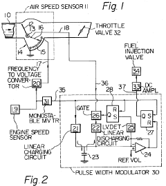
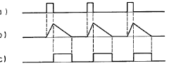
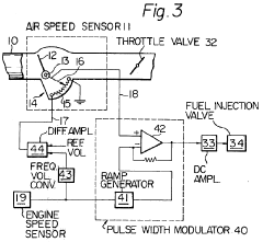
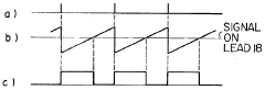
Electronic fuel injection control apparatus using variable resistance for relating intake air speed to engine speed
PatentInactiveUS4121545A
Innovation
- An electromechanical control device that combines sensed air speed and engine speed through a mechanical pivotal movement, using a variable resistance element to modulate voltage and generate variable pulse duration control signals for fuel injection, reducing the need for complex calculating circuits.
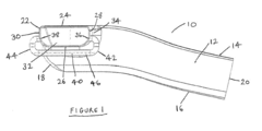
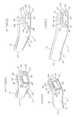
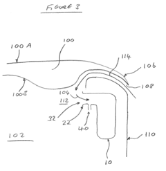
Air intake apparatus
PatentActiveEP2985444A1
Innovation
- An air intake apparatus with an auxiliary pipe that communicates internal regions of the duct at different pressures to reduce velocity variations, preventing particle ingestion and enhancing airflow by allowing fluid communication between these regions.
Materials Science Impact on Intake Efficiency
The advancement of materials science has revolutionized intake efficiency in LS2 engines, offering significant opportunities to improve air speed through the intake duct. Traditional materials like aluminum and plastic have dominated intake system components, but recent innovations in composite materials, ceramics, and specialized metal alloys have opened new possibilities for performance enhancement.
Carbon fiber reinforced polymers (CFRP) represent a breakthrough in intake duct design, providing exceptional strength-to-weight ratios while allowing for complex geometries that optimize airflow. These materials reduce thermal absorption compared to metal components, maintaining lower air temperatures and consequently higher air density entering the combustion chamber. Studies indicate that CFRP intake ducts can improve volumetric efficiency by 2-3% compared to traditional materials.
Surface treatments and coatings have emerged as another critical area of materials science innovation. Nano-scale surface modifications can significantly reduce friction coefficients between the intake air and duct walls. Hydrophobic coatings, originally developed for aerospace applications, have been adapted for automotive intake systems, reducing boundary layer development and minimizing flow separation. These treatments can maintain laminar flow at higher velocities, directly translating to improved air speed through the system.
Thermal management properties of materials play a crucial role in intake efficiency. Ceramic-matrix composites (CMCs) offer excellent thermal insulation characteristics, preventing heat soak from the engine bay affecting intake air temperature. Some manufacturers have implemented selective use of these materials in critical sections of the intake path, creating thermal barriers that preserve intake charge density.
Advanced manufacturing techniques like 3D printing have enabled the production of intake components with internal flow-optimizing structures that would be impossible with traditional manufacturing methods. These include variable wall thicknesses, integrated flow straighteners, and micro-vortex generators that can be precisely positioned to manage boundary layer development.
Material elasticity considerations have also proven important for dynamic flow conditions. Certain elastomeric compounds can dampen pressure waves and reduce resonance effects that disrupt smooth airflow, particularly at high engine speeds. These materials, strategically placed within the intake tract, help maintain consistent air velocity across the RPM range.
The environmental impact of materials selection cannot be overlooked. Newer bio-based composites offer comparable performance to petroleum-derived plastics while reducing carbon footprint. These materials often exhibit excellent vibration damping properties, contributing to more stable airflow characteristics under real-world operating conditions.
Environmental Regulations and Emissions Compliance Considerations
Improving the LS2 engine's intake duct air speed must be considered within the framework of increasingly stringent environmental regulations and emissions standards worldwide. The Environmental Protection Agency (EPA) in the United States and the European Union's Euro standards have established progressively stricter limits on vehicle emissions, particularly focusing on nitrogen oxides (NOx), carbon monoxide (CO), and particulate matter. Any modifications to the LS2 engine's intake system must ensure compliance with these regulations to maintain legal status for on-road use.
Enhanced air speed in the intake duct directly impacts the air-fuel mixture and combustion efficiency, which consequently affects emissions output. Higher air velocity can lead to improved atomization of fuel and more complete combustion, potentially reducing hydrocarbon emissions. However, increased air flow may also raise combustion temperatures, potentially increasing NOx formation if not properly managed through complementary systems such as exhaust gas recirculation (EGR) or advanced catalytic converters.
The California Air Resources Board (CARB) regulations present particular challenges for engine modifications, requiring any aftermarket parts that affect emissions to obtain an Executive Order (EO) number certifying that they do not degrade emissions performance. Manufacturers seeking to improve LS2 intake systems must navigate this certification process, which includes rigorous emissions testing under various operating conditions.
Recent trends in emissions compliance have seen the implementation of On-Board Diagnostics II (OBD-II) systems that continuously monitor emissions performance. Modifications to intake systems must not trigger fault codes or interfere with these monitoring systems, which could result in failed emissions tests or vehicle operation issues. This necessitates careful integration of any air speed enhancement technologies with the engine's electronic control unit (ECU).
Global market considerations also play a significant role, as different regions maintain varying emissions standards. Manufacturers developing improved intake systems for the LS2 must consider whether their solutions can be adapted to meet multiple regulatory frameworks, or if region-specific variants will be necessary. This regulatory fragmentation adds complexity to the development and certification process.
Looking forward, upcoming regulations such as the proposed Euro 7 standards and similar initiatives in other markets will likely impose even stricter emissions limits. This regulatory trajectory suggests that future intake system designs should not only address current compliance requirements but also incorporate flexibility to adapt to evolving standards, potentially through modular designs or programmable electronic controls that can be updated as regulations change.
Unlock deeper insights with Patsnap Eureka Quick Research — get a full tech report to explore trends and direct your research. Try now!
Generate Your Research Report Instantly with AI Agent
Supercharge your innovation with Patsnap Eureka AI Agent Platform!