Al technical title is built by PatSnap Al team. It summarizes the technical point description of the patent document.
A mobile phone camera and camera technology, which is applied in the field of cameras, can solve the problems of reducing the shooting effect of the camera body, scratching the camera body, and lacking the flipping protection function of the camera body.
Active Publication Date: 2019-03-29
安徽中轩信息技术有限公司
View PDF7 Cites 3 Cited by
Summary
Abstract
Description
Claims
Application Information
AI Technical Summary
This helps you quickly interpret patents by identifying the three key elements:
Problems solved by technology
Method used
Benefits of technology
Problems solved by technology
[0004] (1) The present invention proposes a mobile phone camera. By adding a rotating rod, a gear, a rack, a moving rod, a guide rod, a magnetic block and a spring, the main body of the camera is rotated, and the rotation of the main body of the camera drives the rotation of the rotating rod, and the rotation of the rotating rod drives the gear Rotate, the gear rotates to drive the rack to move, the rack moves to drive the moving rod to move, the moving rod moves along the guide rod to stretch the spring, and the spring is stretched to generate elastic force. When the camera body is turned 180°, the moving rod and The magnetic block is attached, and the magnetic block absorbs and fixes the moving rod to protect the main body of the camera. It solves certain defects in the currently used mobile phone camera, lacks the flip protection function of the main body of the camera, and the main body of the camera is exposed to the air. Putting other items together can easily cause scratches to the main body of the camera and reduce the shooting effect of the main body of the camera
Method used
Image
Click on the blue label to locate the original text in one second.
Reading with bidirectional positioning of images and text.
Examples
Embodiment Construction
[0024] The following will clearly and completely describe the technical solutions in the embodiments of the present invention with reference to the accompanying drawings in the embodiments of the present invention. Obviously, the described embodiments are only some, not all, embodiments of the present invention. Based on the embodiments of the present invention, all other embodiments obtained by persons of ordinary skill in the art without making creative efforts belong to the protection scope of the present invention.
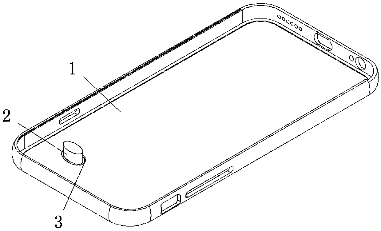
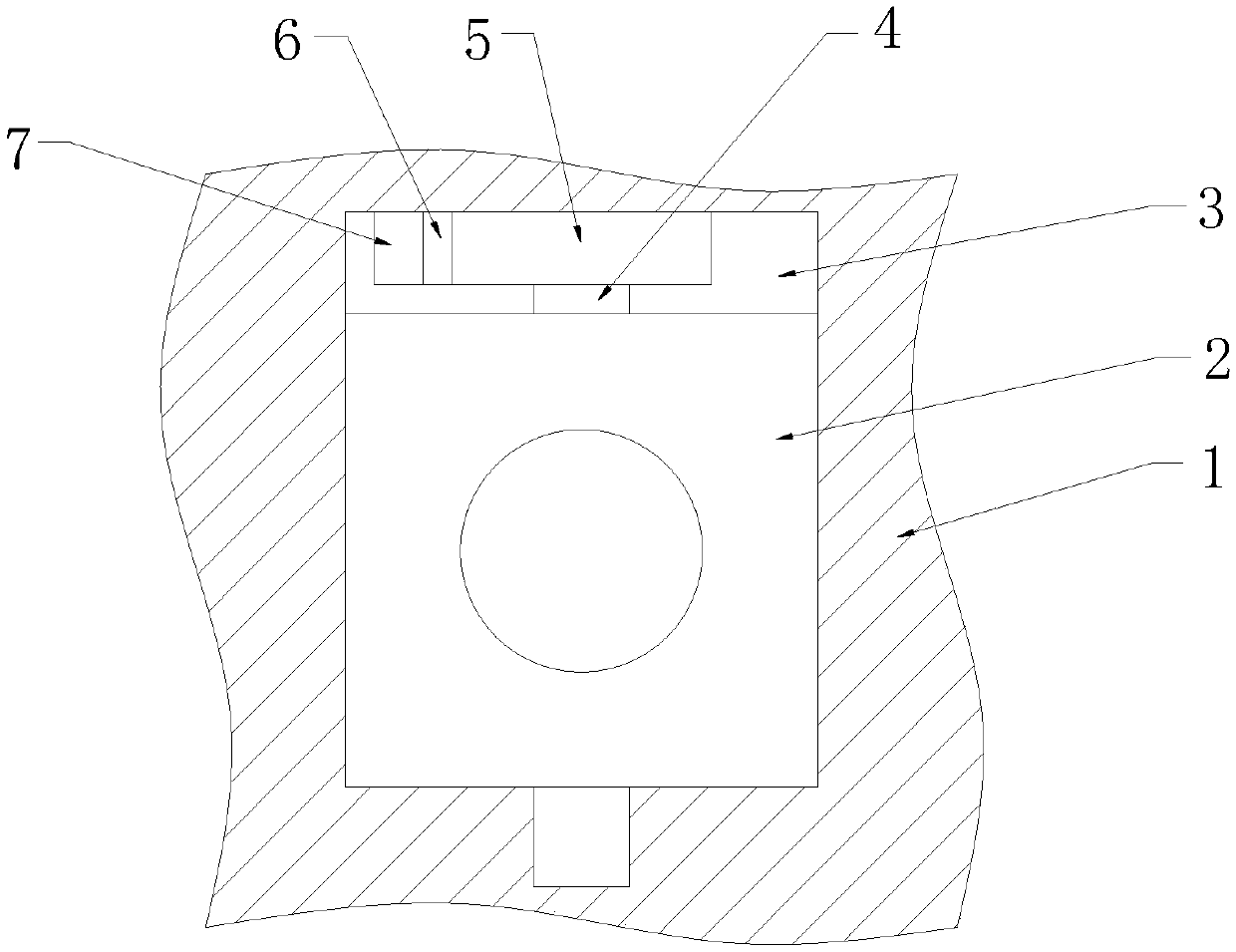
[0025] see Figure 1-5 As shown, a mobile phone camera includes a mobile phone housing 1, a camera body 2, a groove 3, a flip protection mechanism for camera protection, and a reset mechanism for camera reset, and a groove is provided on one side of the mobile phone housing 1 3. The camera main body 2 is installed inside the groove 3;
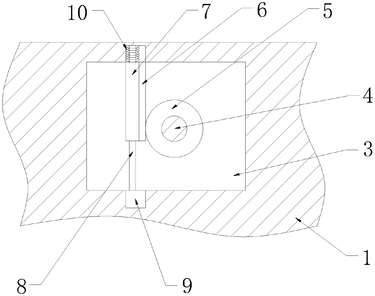
[0026] The overturning protection mechanism comprises a rack 6, a moving bar 7, a guide bar 8, a magnetic block 9 and a spri...
PUM
Abstract
The invention belongs to the technical field of cameras, and particularly discloses a mobile phone camera. The camera includes a mobile phone shell body, a camera main body, a groove a rotating rod, agear, a rack, a moving rod, a guiding rod, a magnetic block, a spring one, a concave block, a pushing rod, a circular plate, a spring two and a circular groove. According to the camera, rotation of the camera main body drives rotation of the rotating rod, rotation of the rotating rod drives rotation of the gear, rotation of the gear drives moving of the rack, moving of the rack drives moving of the moving rod, and moving of the moving rod stretches the spring one; and when the camera main body is flipped by 180 degrees, the moving rod is attached to the magnetic block, the magnetic block adsorbs and fixes the moving rod, a protection function of the camera main body is achieved, the pushing rod is pushed, moving of the pushing rod drives moving of the concave block, the concave block moves to be attached to the moving rod, then the moving rod is pressed to be separated from the magnetic block, the moving rod moves to return to an original position under the action of elastic force ofthe spring one, moving of the moving rod drives moving of the rack, moving of the rack drives rotation of the sliding gear, and flipping of the camera main body is realized.
Description
technical field [0001] The invention belongs to the technical field of cameras, in particular to a mobile phone camera. Background technique [0002] The digital camera function of the mobile phone refers to whether the mobile phone can take still pictures or short videos through the built-in or external digital camera. As a new additional function of the mobile phone, the digital camera function of the mobile phone has been developed rapidly. With the improvement of camera pixels, its shooting effect is getting closer and closer to that of traditional cards. [0003] There are certain defects in the currently used mobile phone cameras, lacking the flip protection function of the camera body, the camera body is exposed to the air, and the phone case and other items are put together, which is easy to cause scratches to the camera body and reduce the shooting effect of the camera body. Reset mechanism, it is inconvenient for the camera body to reset after the camera body is r...
Claims
Application Information
Patent Timeline
Application Date:The date an application was filed.
Publication Date:The date a patent or application was officially published.
First Publication Date:The earliest publication date of a patent with the same application number.
Issue Date:Publication date of the patent grant document.
PCT Entry Date:The Entry date of PCT National Phase.
Estimated Expiry Date:The statutory expiry date of a patent right according to the Patent Law, and it is the longest term of protection that the patent right can achieve without the termination of the patent right due to other reasons(Term extension factor has been taken into account ).
Invalid Date:Actual expiry date is based on effective date or publication date of legal transaction data of invalid patent.