Combined electrolytic machining tool cathode and method for improving flatness of machined bottom surface

A technology for machining tools and tool cathodes, which is used in machining electrodes, electrode manufacturing, electric machining equipment, etc., and can solve the problems that the radial size of the rectangular electrode cannot be further reduced, the diameter of the tube electrode is small, and the localization is reduced. Inhibits stray corrosion and overcutting, improves process economy, and results in quick and easy installation

Active Publication Date: 2020-12-18
NANJING UNIV OF AERONAUTICS & ASTRONAUTICS
View PDF11 Cites 0 Cited by
  • Summary
  • Abstract
  • Description
  • Claims
  • Application Information

AI Technical Summary

Problems solved by technology

However, due to the uneven power distribution in the feed direction, the flatness of the processed bottom surface is relatively poor.
In order to reduce stray corrosion, the tube electrode must be insulated, but the insulating layer covered later is easy to fall off due to the high temperature generated during the electrochemical discharge process, which will cause problems such as poor processing stability
In addition, due to the relatively small diameter of the tube electrode, the one-time processing range is limited, and the processing efficiency needs to be further improved.
Compared with the tube electrode, the uniformity of the electricity distribution on the bottom surface of the rectangular electrode in the feeding direction has been greatly improved; due to the internal spray liquid supply mode, the processed surface of the rectangular electrode should have a liquid outlet, which The radial size of the rectangular electrode is limited and cannot be further reduced
Compared with the tube electrode, the wide and thick processing surface of the rectangular electrode leads to a greatly reduced localization, and the overcut and stray corrosion of the processed bottom surface are more serious
In patents CN105921834A, CN108393547A, CN108080755A, etc., successively proposed tool cathodes and methods for improving the flatness of the bottom surface of electrolytic machining, but the surface of these tool cathodes has a large overcut value, and for the design of the bottom insulation, in the electrochemical discharge The high temperatures generated during the process are likely to render it ineffective
This greatly limits the application of electrolytic milling in machining planes, three-dimensional surfaces and cavities

Method used


Image

  • Combined electrolytic machining tool cathode and method for improving flatness of machined bottom surface
  • Combined electrolytic machining tool cathode and method for improving flatness of machined bottom surface
  • Combined electrolytic machining tool cathode and method for improving flatness of machined bottom surface

Examples


Embodiment 1

[0037] like Figure 7 As shown, for blocky workpiece 25:

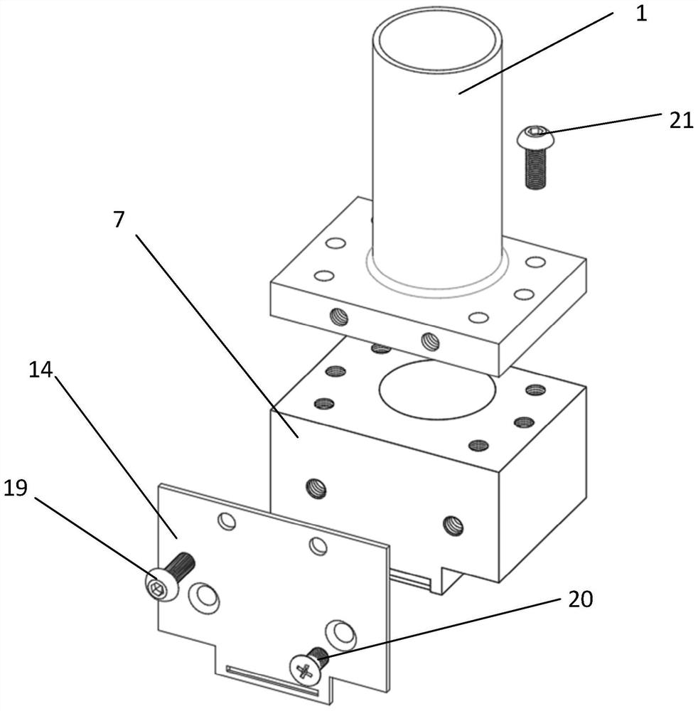
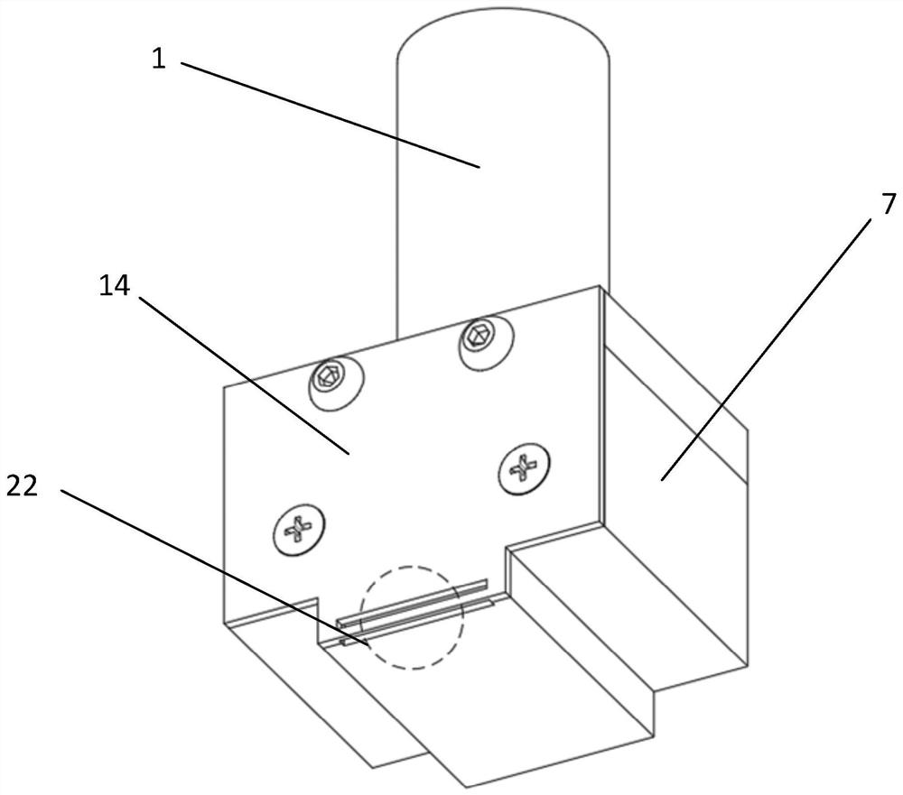
[0038] Step 1: Clamp the tool handle 1 vertically on the spindle of the machine tool, connect the negative pole of the power supply 24 to the cathode of the tool, and connect the positive pole of the power supply 24 to the workpiece, and the liquid outlet 17 on the side of the conductive plate is facing the massive workpiece 25. The cutting depth of the tool cathode is the outlet on the side of the conductive plate Within the range of 1-2 times the distance from the top of the liquid port 17 to the bottom of the conductive plate 14;

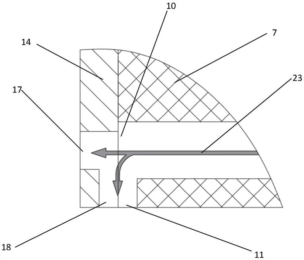
[0039] Step 2: Turn on the switch of the electrolyte 23, the electrolyte 23 flows into the central blind hole 13 of the insulating block 7 along the central through hole 3 of the handle 1, and finally flows to the processing gap along the liquid outlet 17 on the side of the conductive plate and the liquid outlet on the bottom surface of the tool cathode ;

[0040] Step 3: During process...

Embodiment 2

[0042] like Figure 8 As shown, for the shaft workpiece 27:

[0043] Step 1: Clamp the tool holder 1 vertically on the spindle of the machine tool, connect the negative pole of the power supply 24 to the cathode of the tool, and connect the positive pole of the power supply 24 to the workpiece, and the liquid outlet 17 on the bottom of the conductive plate is facing the side of the shaft workpiece 27;

[0044] Step 2: keep the shaft workpiece 27 still, cut the tool cathode radially along the shaft workpiece 27, and the processing depth is within 1-2 times of the distance from the top of the liquid outlet 17 on the side of the conductive plate to the bottom of the conductive plate 14;

[0045] Step 3: keep the cathode of the tool still, the shaft workpiece 27 rotates along the rotation direction 28 of the shaft workpiece, and the electrolyte 23 flowing out from the liquid outlet 17 on the side of the conductive plate and the liquid outlet on the bottom surface of the tool catho...


PUM

PropertyMeasurementUnit
Thicknessaaaaaaaaaa

Abstract

The invention relates to a combined electrolytic machining tool cathode and method, and belongs to the field of electrolytic machining. The tool cathode comprises a knife handle, an insulating block,a current-conducting plate, an electricity leading screw and a fastening screw. The combined electrolytic machining tool cathode aims to solve the problems of stray corrosion, poor flatness of bottomsurface and the like generated when a rod-shaped cathode tool is used for machining a groove. The current-conducting plate with the thickness smaller than 1 mm is used, and a current-conducting area between a cutter and a machined surface is limited. Compared with a previous circular current-conducting area, the bottom current-conducting area is greatly reduced, electric quantity distribution of the bottom of a machining groove in the radial feeding direction of a tool cathode is equal everywhere, and the flatness of the bottom of the groove in electrolytic machining is effectively improved; and the long insulating boss and the insulating area with the width larger than that of the machined groove are designed, resistance and back pressure of electrolyte flowing through the machined surface from the bottom of the cutter are increased, flow field of the machining area is improved, and stray corrosion is effectively restrained.

Description

technical field [0001] The invention relates to a tool cathode and a method for suppressing stray corrosion and overcutting phenomena in the electrolytic machining process and improving the flatness of the processed bottom surface, belonging to the field of electrolytic machining. Background technique [0002] The development level of the aerospace industry reflects the comprehensive strength of a country's economy and manufacturing industry, and the aerospace industry has put forward higher requirements for the performance of aircraft and engine structural parts and main materials. Due to the advantages of high-temperature alloys, titanium alloys and other difficult-to-machine materials, such as good rigidity, high specific strength, and relatively light weight, they have been widely used in the aerospace industry. For example, GH4169 material accounts for 34%, 56% and 57% of the total weight of CF6 engine, CY2000 engine and PW4000 engine respectively. However, due to the ...

Claims


Application Information

Patent Timeline
IPC IPC(8): B23H3/06
CPCB23H3/06
Inventor 马鑫李寒松曲宁松岳小康
Owner NANJING UNIV OF AERONAUTICS & ASTRONAUTICS
Why Eureka
Try Eureka