Airbag apparatus

a technology of airbags and airbag bodies, which is applied in the direction of pedestrian/occupant safety arrangements, vehicular safety arrangments, vehicle components, etc., can solve the problems of undesirable direction, inability to deploy and inflate the airbag body, etc., and achieves the effect of preventing downward deployment and inflation of the airbag body, reducing the displacement of the folded portion, and facilitating the deploymen

Inactive Publication Date: 2008-10-02
TOYODA GOSEI CO LTD
View PDF13 Cites 13 Cited by
  • Summary
  • Abstract
  • Description
  • Claims
  • Application Information

AI Technical Summary

Benefits of technology

[0009]To achieve the foregoing objective and in accordance with one aspect of the present invention, an airbag apparatus having an airbag body arranged between a roof panel and a roof head lining of a vehicle and held in a folded state is provided. The airbag apparatus includes a fixing member fixing the airbag body to the roof panel, a binding member, and a restricting member. The airbag body has a fixed portion fixed by the fixing member and a folded portion that extends from the fixed portion and is maintained in a folded state. The binding member binds the folded portion and releases the folded portion when the airbag body is deployed and inflated. The restricting member restricts downward displacement of the folded portion while ensuring an open space below the folded portion when the airbag body is fixed to the roof panel.
[0010]In this structure, the binding member binds the folded portion of the airbag body together, thus maintaining the airbag body in a folded state. The airbag body has the fixed portion fixed by the fixing member and the folded portion extending from the fixed portion and held in a folded state. Since the apparatus according to the present invention has the restricting member that restricts downward displacement of the folded portion, the folded portion is prevented from hanging down due to its own weight. Further, since the restricting member ensures an open space below the folded portion, downward deployment and inflation of the airbag body are prevented from being hindered by the restricting member. This allows the airbag body to be smoothly deployed and inflated downward along inner walls of the vehicle and prevents the airbag body from hanging down when the airbag apparatus is installed. If a roof head lining guides the airbag body so that the airbag body is deployed and inflated in a desired direction, inflation of the airbag body is prevented from being hindered by the restricting member.

Problems solved by technology

This makes it impossible to deploy and inflate the airbag body 113 in a desired direction, which is also disadvantageous.
Such problems are common for airbag apparatuses having airbag bodies installed between roof panels and roof head linings of vehicles and held in folded states, other than airbag apparatuses for rear-end collision.

Method used


Image

  • Airbag apparatus
  • Airbag apparatus
  • Airbag apparatus

Examples


first embodiment

[0026]A first embodiment of an airbag apparatus according to the present invention, which is an airbag apparatus for rear-end collision secured to a minivan or a hatchback, will hereafter be described with reference to FIGS. 1 to 6.

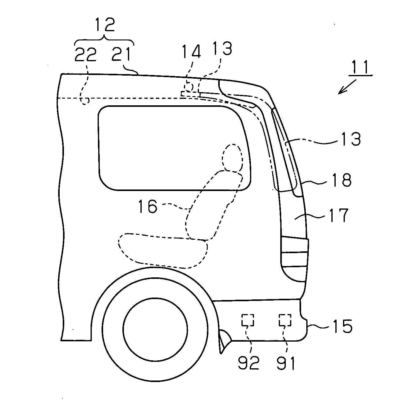
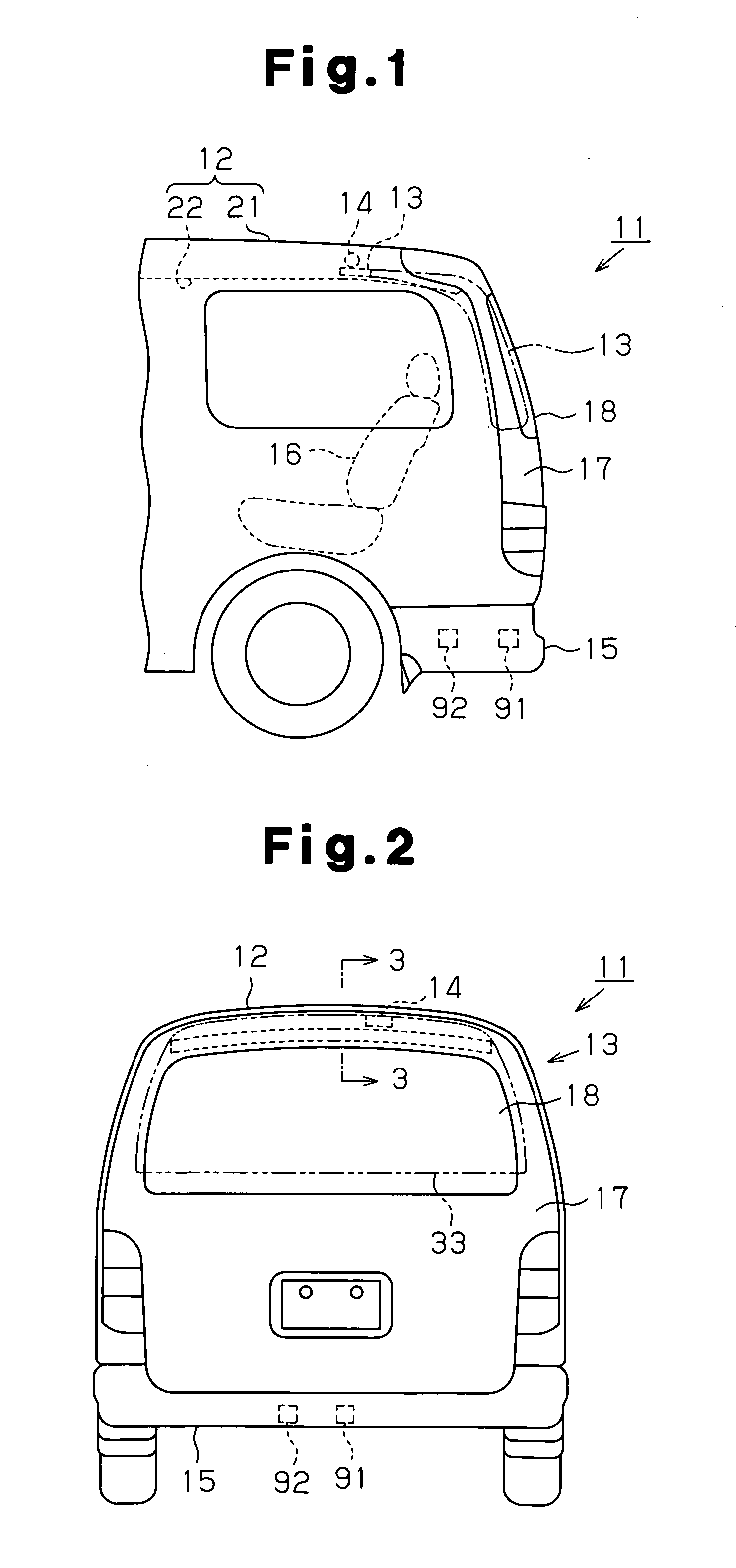
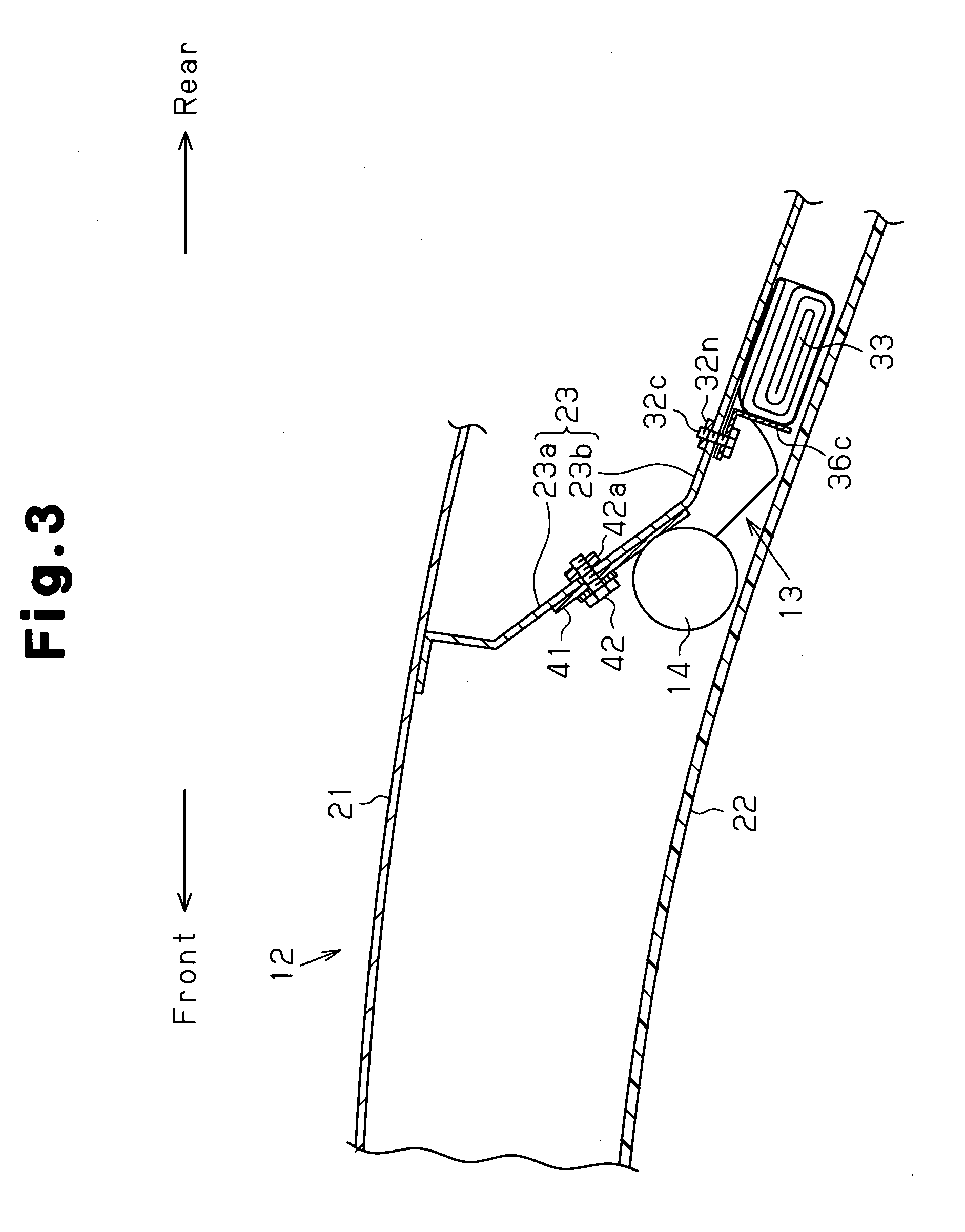
[0027]As shown in FIGS. 1 and 2, an airbag apparatus for rear-end collision including an inflator 14 and an airbag body 13 is secured to a rear portion of a roof 12 of a vehicle 11. The inflator 14 generates gas to deploy and inflate the airbag body 13. The airbag body 13 is arranged rearward from the inflator 14 and held in a folded state.

[0028]A sensor 91 detecting impact from the rear of the vehicle 11 and a controller 92 are provided in a rear bumper 15 of the vehicle 11. The controller 92 outputs an actuation signal commanding the inflator 14 to generate gas in accordance with a detection result of the sensor 91. If a rear-end collision happens, the inflator 14 generates the gas in response to the actuation signal. This deploys and inflates the airba...

second embodiment

[0047]An airbag apparatus according to a second embodiment of the present invention will hereafter be described with reference to FIGS. 7 and 8. The description focuses on the differences between the second embodiment and the first embodiment.

[0048]As shown in FIG. 7, in the second embodiment, T-shaped restricting plates 236 are arranged above the fixed pieces 31a to 31c of an airbag body 213. This structure prevents the folded portions 33 from hanging down. The restricting plates 236 are shaped identically.

[0049]Each of the T-shaped restricting plates 236 is formed by a flat plate of steel. Each of the restricting plates 236 has a proximal portion 236a and a support plate portion 236b. The proximal portion 236a has a rectangular shape in correspondence with each of the fixing plates 31a to 31c of the airbag body 213. The support plate portion 236b has a rectangular shape and extends from the proximal portion 236a in a rearward direction (downward as viewed in FIG. 7) and in the dir...

third embodiment

[0059]An airbag apparatus according to a third embodiment of the present invention will now be described with reference to FIG. 9. The following description focuses on the differences between the third embodiment and the first and second embodiments.

[0060]As shown in FIG. 9, left and right binding tapes 335B are wound around the outer circumference of the folded portion 33 to bind the folded portion 33 together, as in the first embodiment. The binding tapes 335B maintain the airbag body 313 in a folded state when an airbag body 313 is secured to the guide portion 23b of the inner panel 23 (the roof panel 21). When the airbag body 313 is deployed and inflated, the binding tapes 335B break to release the airbag body 313. In a fully deployed and inflated state, the folded portion 33 has a substantially rectangular bag-like shape as shown in FIG. 2.

[0061]When the airbag body 313 is fixed to the guide portion 23b of the inner panel 23 (the roof panel 21), a ring 336c is secured to a rear...


PUM


Abstract

An airbag apparatus has an airbag body, which is arranged between a roof panel and a roof head lining of a vehicle and held in a folded state. The airbag body also has a second bolt, a fixed piece, and a folded portion. The airbag body is fixed to a guide portion of an inner panel by the second bolt. The fixed piece is fixed by the second bolt. The folded portion extends from the fixed piece and is maintained in a folded state. The airbag body also includes a binding tape and a restricting plate. The binding tape binds the folded portion together and releases the folded portion when the airbag body is deployed and inflated. The restricting plate ensures an open space below the folded portion and restricts downward displacement of the folded portion when the airbag body 13 is fixed to the guide portion.

Description

BACKGROUND OF THE INVENTION[0001]The present invention relates to an airbag apparatus having an airbag body installed between a roof panel and a roof head lining of a vehicle and held in a folded state.[0002]Conventionally, Japanese Laid-Open Patent Publication No. 2005-104172 discloses one such type of airbag apparatus. FIG. 13 schematically shows a typical airbag apparatus for rear-end collision of a vehicle, including the apparatus of this document.[0003]As shown in FIG. 13, the airbag apparatus for rear-end collision includes an airbag body 113 mounted between a roof panel 21 and a roof head lining 22 of a vehicle 11 and held in a folded state. In a rear end collision of the vehicle 11, an inflator 14 supplies gas to the airbag body 113, thus deploying and inflating the airbag body 113 into a space rearward from a rear seat with respect to the vehicle.[0004]Specifically, with reference to FIG. 14, the airbag body 113 has a plurality of fixed pieces 131a, 131b, 131c, which are fi...

Claims


Application Information

Patent Timeline
Patent Type & Authority Applications(United States)
IPC IPC(8): B60R21/213B60R21/201B60R21/20
CPCB60R21/201B60R21/214B60R21/232B60R2021/0011B60R2021/23153
Inventor IIDA, TAKASHIYAMANAKA, MAKOTOOCHIAI, YASUOMIZUNO, YOSHIO
Owner TOYODA GOSEI CO LTD
Why Eureka
Try Eureka