Mold cased circuit breaker

a circuit breaker and case technology, applied in circuit breaker details, high-tension/heavy-dress switches, air-break switches, etc., can solve problems such as lowering circuit characteristics

Active Publication Date: 2011-12-08
LSIS CO LTD
View PDF6 Cites 2 Cited by
  • Summary
  • Abstract
  • Description
  • Claims
  • Application Information

AI Technical Summary

Benefits of technology

[0013]Therefore, an aspect of the detailed description is to provide an arc-extinguishing unit for a mold cased circuit breaker capable of pr

Problems solved by technology

Furthermore, the debris may be spread into the main body of the circuit breaker to thereby affect other components of the circuit breaker including the switching mechanism 40.
Th

Method used


Image

  • Mold cased circuit breaker
  • Mold cased circuit breaker
  • Mold cased circuit breaker

Examples


Embodiment Construction

[0030]Description will now be given in detail of the exemplary embodiments, with reference to the accompanying drawings. For the sake of brief description with reference to the drawings, the same or equivalent components will be provided with the same reference numbers, and description thereof will not be repeated.

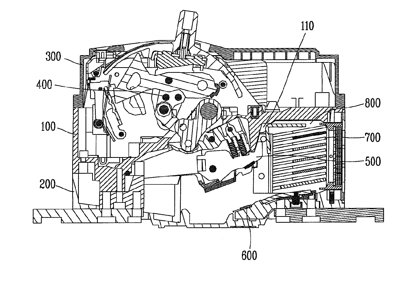
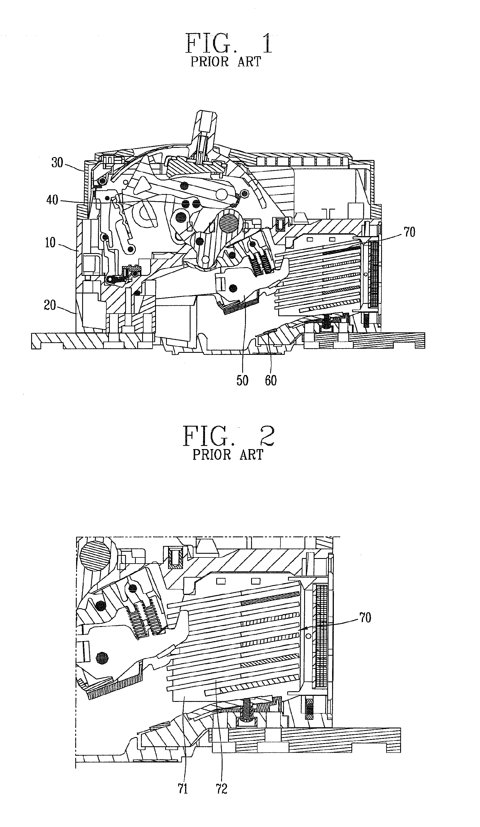
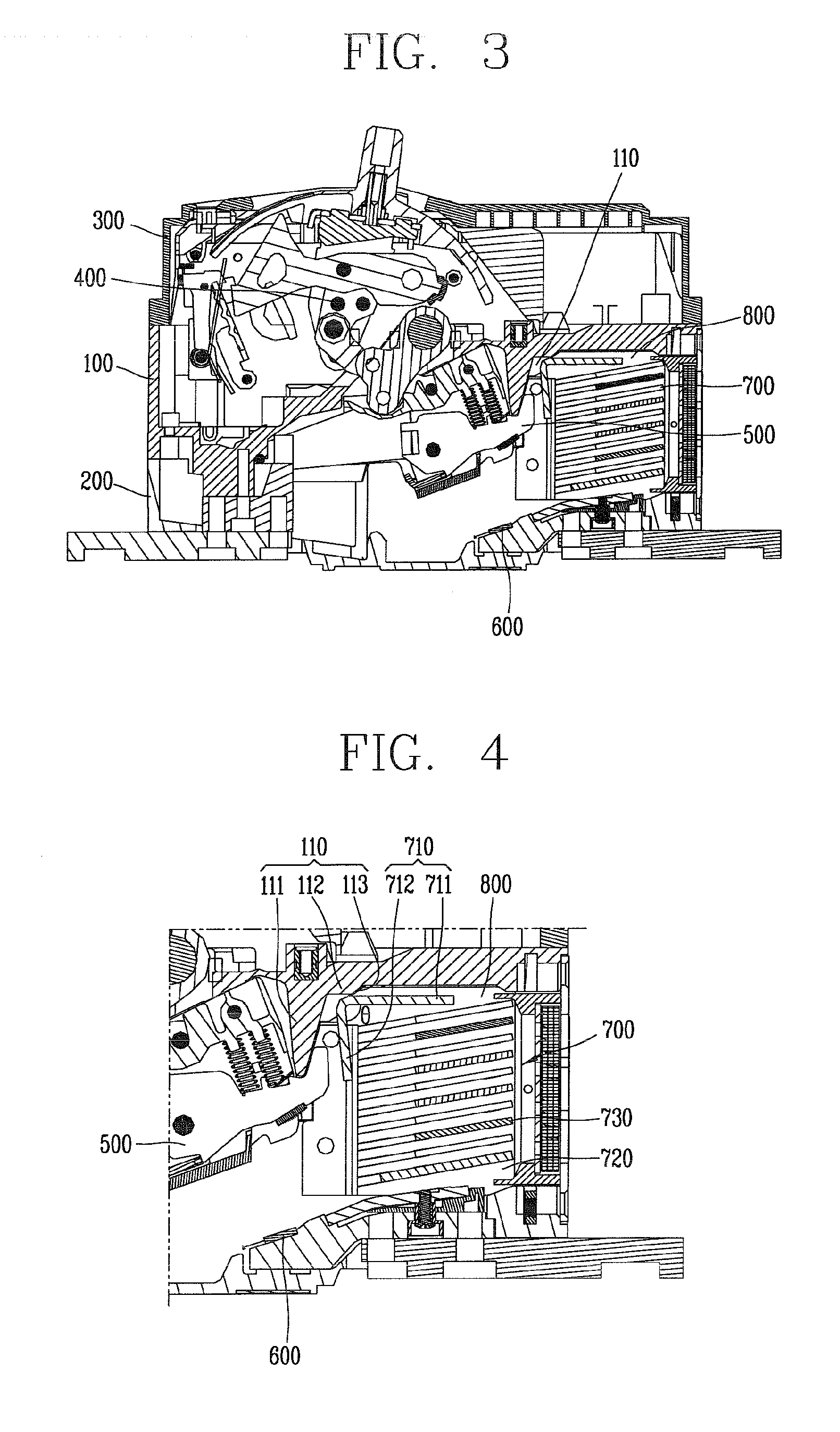
[0031]FIG. 3 is a side sectional view of a mold cased circuit breaker in accordance with this specification, FIG. 4 is an enlarged view of an arc-extinguishing unit (after separation) of FIG. 3, FIG. 5 is an enlarged view of the arc-extinguishing unit (before separation) of FIG. 3, FIG. 6 is a view showing a lower surface of the arc-extinguishing unit, and FIG. 7 is a front view of the arc-extinguishing unit of FIG. 6 shown in an upside down state.

[0032]As shown in FIG. 3, a mold cased circuit breaker according to this specification may include a casing for accommodating components therein and allowing insulation from the exterior, a switching mechanism 400 disposed in the...


PUM


Abstract

A mold cased circuit breaker, which includes a casing, a switching unit disposed in the casing to open or close an electric circuit, and movable and stationary contactor units present within the casing, includes an arc-extinguishing unit. The arc-extinguishing unit includes a pair of side plates facing each other with being spaced from each other, at least one first grid arranged between the side plates and spaced apart from one another with preset intervals, and a second grid coupled to upper ends of the side plates, spaced apart from the first grid, and having a bent portion with a preset angle.

Description

CROSS-REFERENCE TO RELATED APPLICATION[0001]Pursuant to 35 U.S.C. §119(a), this application claims the benefit of earlier filing date and right of priority to Korean Application No. 10-2010-0053065, filed on Jun. 4, 2010, the contents of which is incorporated by reference herein in its entirety.BACKGROUND OF THE INVENTION[0002]1. Field of the Invention[0003]This specification relates to a mold cased circuit breaker capable of fast extinguishing arc, which is generated when a movable contactor is separated from a stationary contactor due to a fault current, by segmenting and cooling the generated arc and discharging arc pressure to the outside.[0004]2. Background of the Invention[0005]Generally, a mold cased circuit breaker is an electric protection apparatus, which is installed in an electric circuit to protect the circuit by preventing or minimizing damages on load equipment and lines due to fault currents (e.g., overload, short-circuit, etc.).[0006]The circuit breaker typically in...

Claims


Application Information

Patent Timeline
IPC IPC(8): H01H33/08
CPCH01H73/18H01H9/362
Inventor AN, YOUNG GYU
Owner LSIS CO LTD
Why Eureka
Try Eureka