Digital multimeter

Inactive Publication Date: 2012-11-29
HONG FU JIN PRECISION IND (SHENZHEN) CO LTD +1
View PDF5 Cites 0 Cited by
  • Summary
  • Abstract
  • Description
  • Claims
  • Application Information

AI Technical Summary

Problems solved by technology

However, in practice, after two detecting pins of the digital multimeter are used to contact electrica...

Method used


Image

  • Digital multimeter
  • Digital multimeter
  • Digital multimeter

Examples


Embodiment Construction

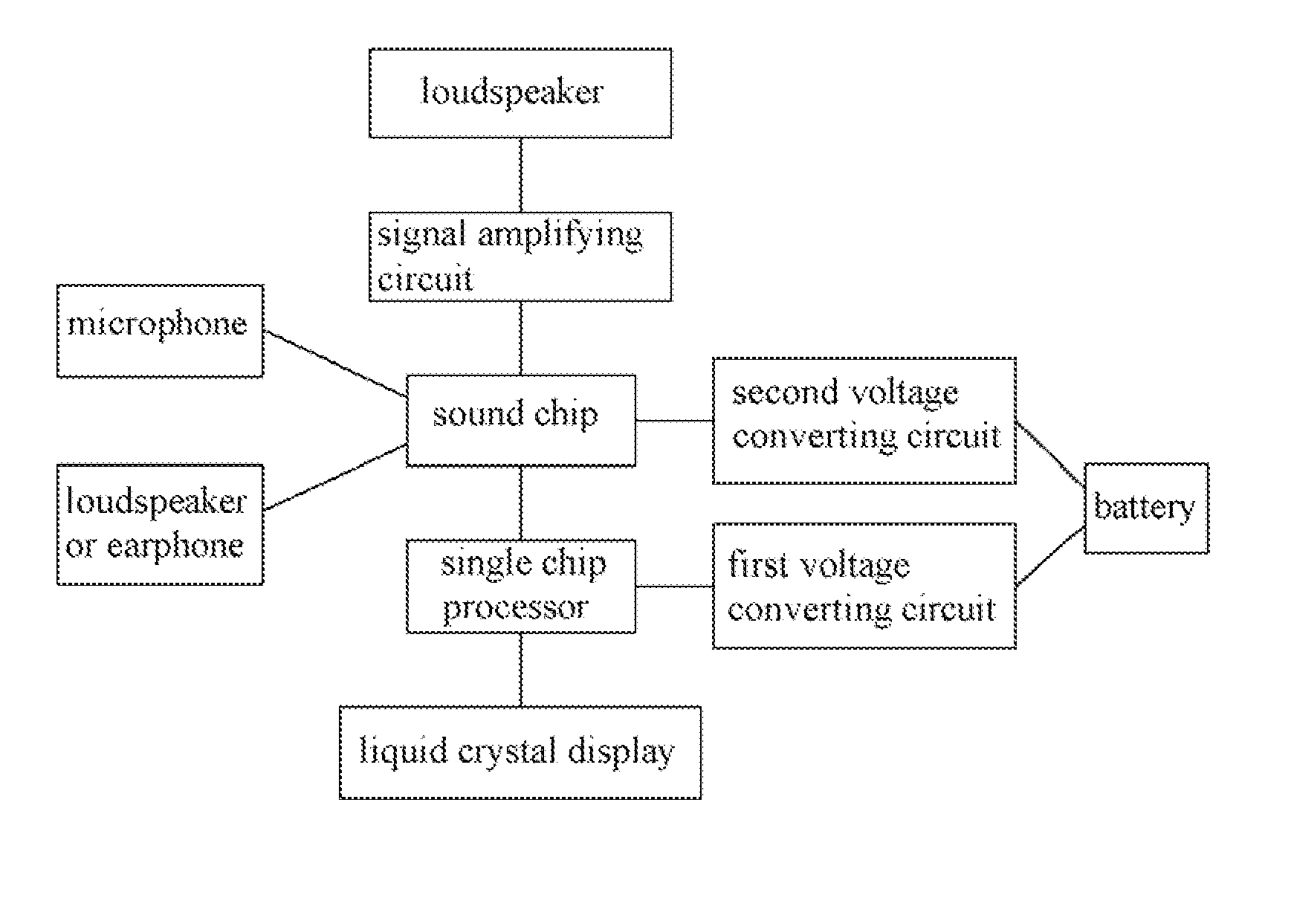
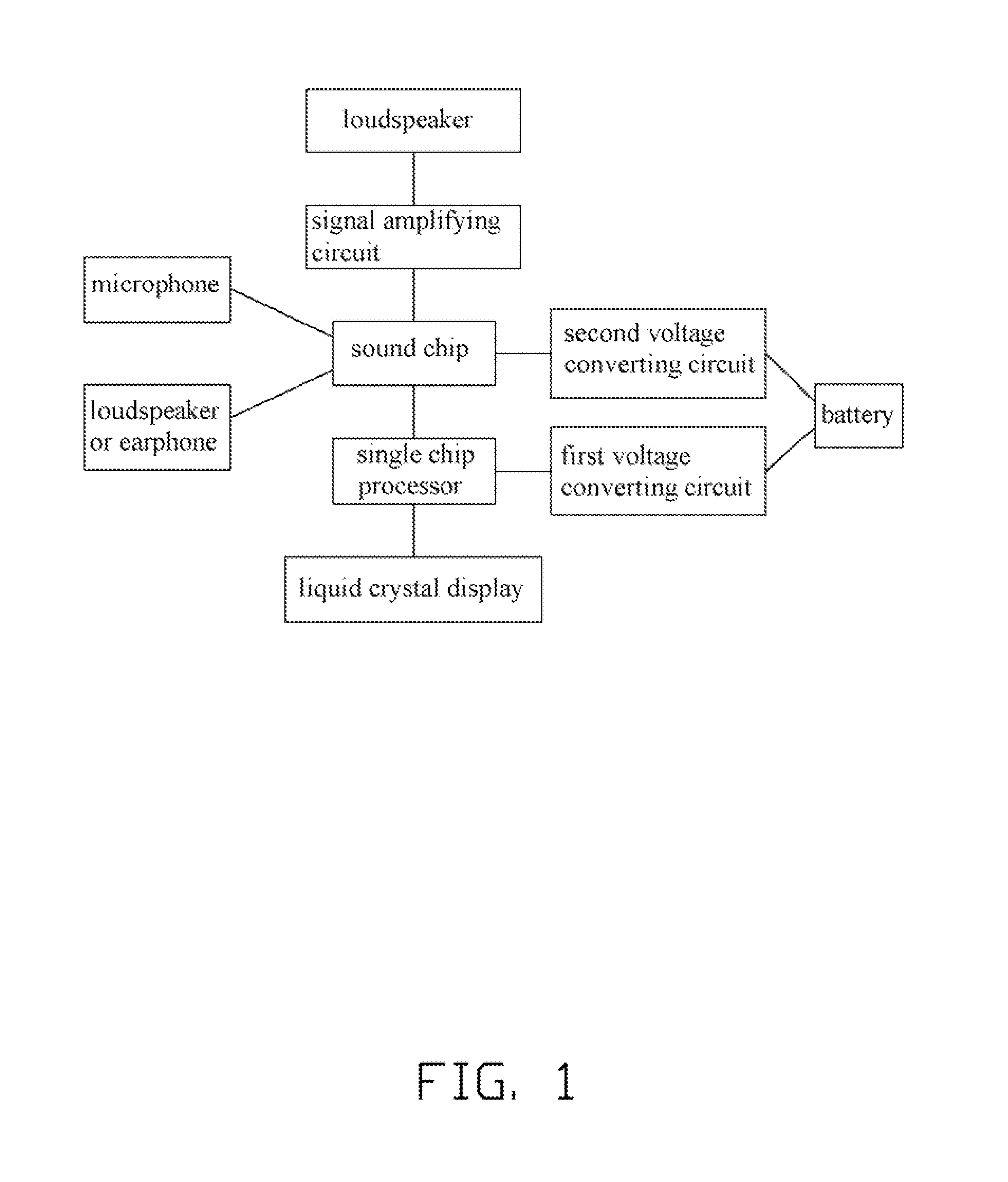
[0008]Referring to FIGS. 1 and 2, a digital multimeter according to an exemplary embodiment of the disclosure includes a single chip processor U1, a sound chip U2, a signal amplifying circuit, a speaker LS, and a battery providing power for the digital multimeter.

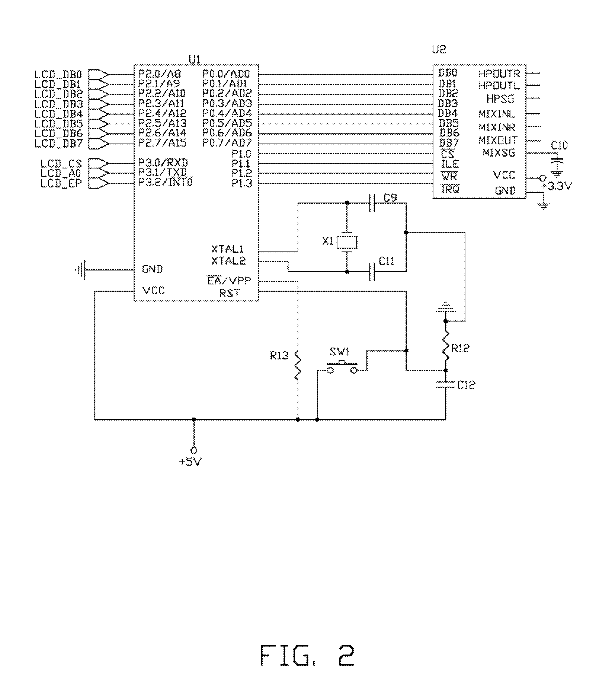
[0009]In this embodiment, the type of the single chip processor U1 is AT89C51, and includes an input / output port P2 which includes eight pins P2.0-P2.7, and an input / output port P0 which includes eight pins P0.0-P0.7. The parallel input / output port P2 (i.e. Pins P2.0-P2.7) of the single chip processor U1 correspondingly connect to the signal pins LCD_DB0-LCD_DB7 of a liquid crystal display (LCD) of the digital multimeter to collect the measurement values of the digital multimeter. The high and low level signals collected are converted into codes via the programs in the single chip processor U1. The codes are then transmitted to the sound chip U2. A pin RXD of the single chip processor U1 connects to a pin LCD_CS of the LCD....


PUM


Abstract

A digital multimeter includes a single chip processor, a sound chip connected to the single chip processor, a signal amplifying circuit, a speaker connected to the signal amplifying circuit, and a power source for providing electrical energy for the digital multimeter. The single chip processor collects high and low level signals, and converts the signals into codes which the sound chip can recognize, and transmits the codes to the sound chip. The sound chip converts the codes into audio signals and transmits the audio signals to the signal amplifying circuit. The signal amplifying circuit amplifies the audio signals and outputs the amplified audio signals to the speaker. The amplified audio signals reports the measurement values of the digital multimeter.

Description

BACKGROUND[0001]1. Technical Field[0002]The present disclosure relates to digital multimeters, and particularly to a digital multimeter capable of reporting measurement values.[0003]2. Description of Related Art[0004]As measuring instruments in electronic technologies, digital multimeters are widely used to measure amperage, resistance, voltage, etc. Digital multimeters have the advantages of displaying measurement values directly and precisely. However, in practice, after two detecting pins of the digital multimeter are used to contact electrical nodes on a circuit board, the operator has to be able to read the measurement values on the display screen.[0005]What is needed, therefore, is a digital multimeter which can overcome the limitations described.BRIEF DESCRIPTION OF THE DRAWINGS[0006]FIG. 1 is a block diagram of a digital multimeter in accordance with an exemplary embodiment of the disclosure.[0007]FIGS. 2-5 each show a different part of the circuit of the digital multimeter ...

Claims


Application Information

Patent Timeline
IPC IPC(8): G01R11/57
CPCG01R15/125
Inventor SONG, YONG-JUNXI, CHUN-FANG
Owner HONG FU JIN PRECISION IND (SHENZHEN) CO LTD
Why Eureka
Try Eureka