Shape measuring machine and method of correcting shape measurement error

a technology of shape measurement and measuring machine, which is applied in the direction of measuring device, mechanical measuring arrangement, instruments, etc., can solve the problems of affecting the measurement accuracy of the measurement, unable to eliminate the measurement error, and noticeable relative displacement, etc., and achieve the effect of removing the measurement error

Active Publication Date: 2014-05-15
MITUTOYO CORP
View PDF8 Cites 16 Cited by
  • Summary
  • Abstract
  • Description
  • Claims
  • Application Information

AI Technical Summary

Benefits of technology

[0009]However, the inventors have found that there is the following problem in the above-described technique. The above-described technique disclosed in Japanese Unexamined Patent Application Publication No. 2007-315897 can eliminate the measurement error resulting from the frequency transfer characteristic between the scale unit, which detects the displacement amount of the probe through the slider of the coordinate measuring machine, and the tip of the slider. However, depending of the type of the probe used in the scanning measurement, a relative displacement between the position of the tip of the slider and the reference position of the tip sphere of the scanning probe could

Problems solved by technology

However, the inventors have found that there is the following problem in the above-described technique.
The relative displacement like this becomes noticeable when the response of the scanning probe is poor and thus the reference position of the tip sphere of the scanning probe cannot follow the moveme

Method used


Image

  • Shape measuring machine and method of correcting shape measurement error
  • Shape measuring machine and method of correcting shape measurement error
  • Shape measuring machine and method of correcting shape measurement error

Examples


first exemplary embodiment

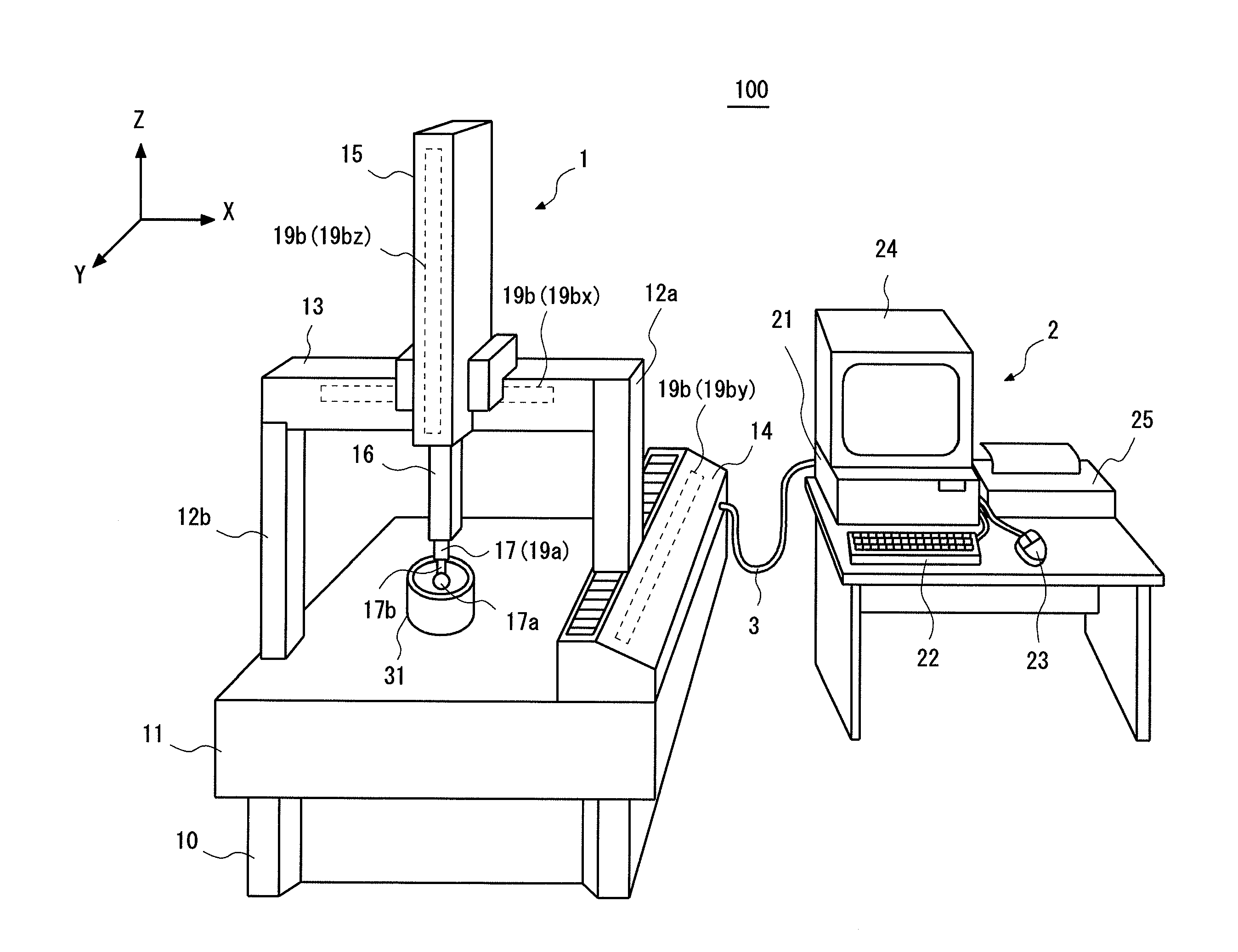
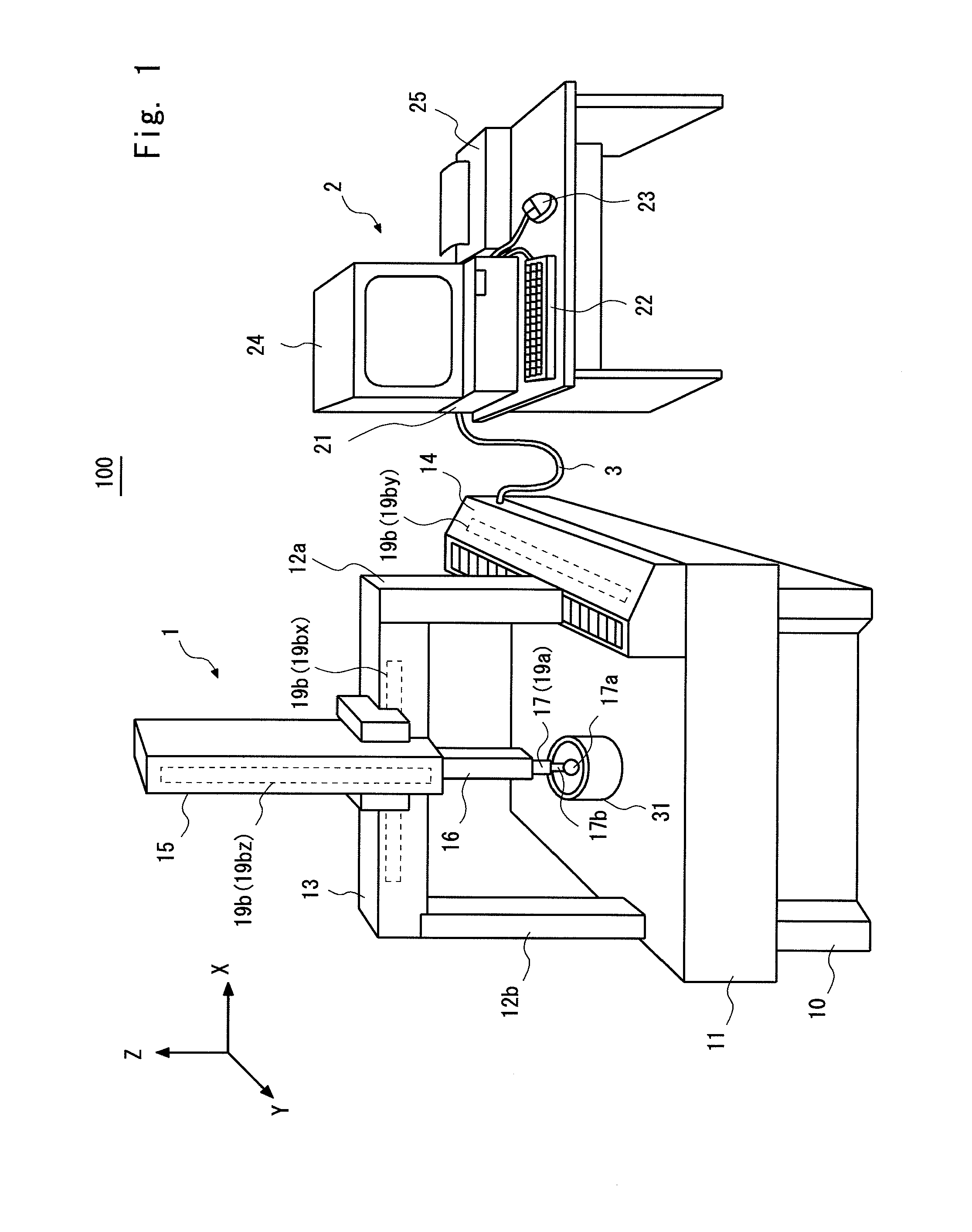
[0032]Firstly, a shape measuring machine 100 according to a first exemplary embodiment is explained. FIG. 1 is a perspective view schematically showing a configuration of a shape measuring machine 100 according to a first exemplary embodiment. The shape measuring machine 100 includes a coordinate measuring machine 1 and a computer 2. The coordinate measuring machine 1 is connected to the computer 2 through a cable 3.

[0033]The coordinate measuring machine 1 is configured as shown in FIG. 1, for example, in which a surface plate 11 is mounted on a vibration damping pedestal 10 in such a manner that the upper surface (base surface) of the surface plate 11 coincides with the horizontal plane (XY-plane in FIG. 1). A Y-axis driving mechanism 14 that extends in the Y-direction is disposed at one end of the surface plate 11 in the X-direction. A beam support 12a is disposed in a standing position on the Y-axis driving mechanism 14. In this manner, the Y-axis driving mechanism 14 can drive t...

second exemplary embodiment

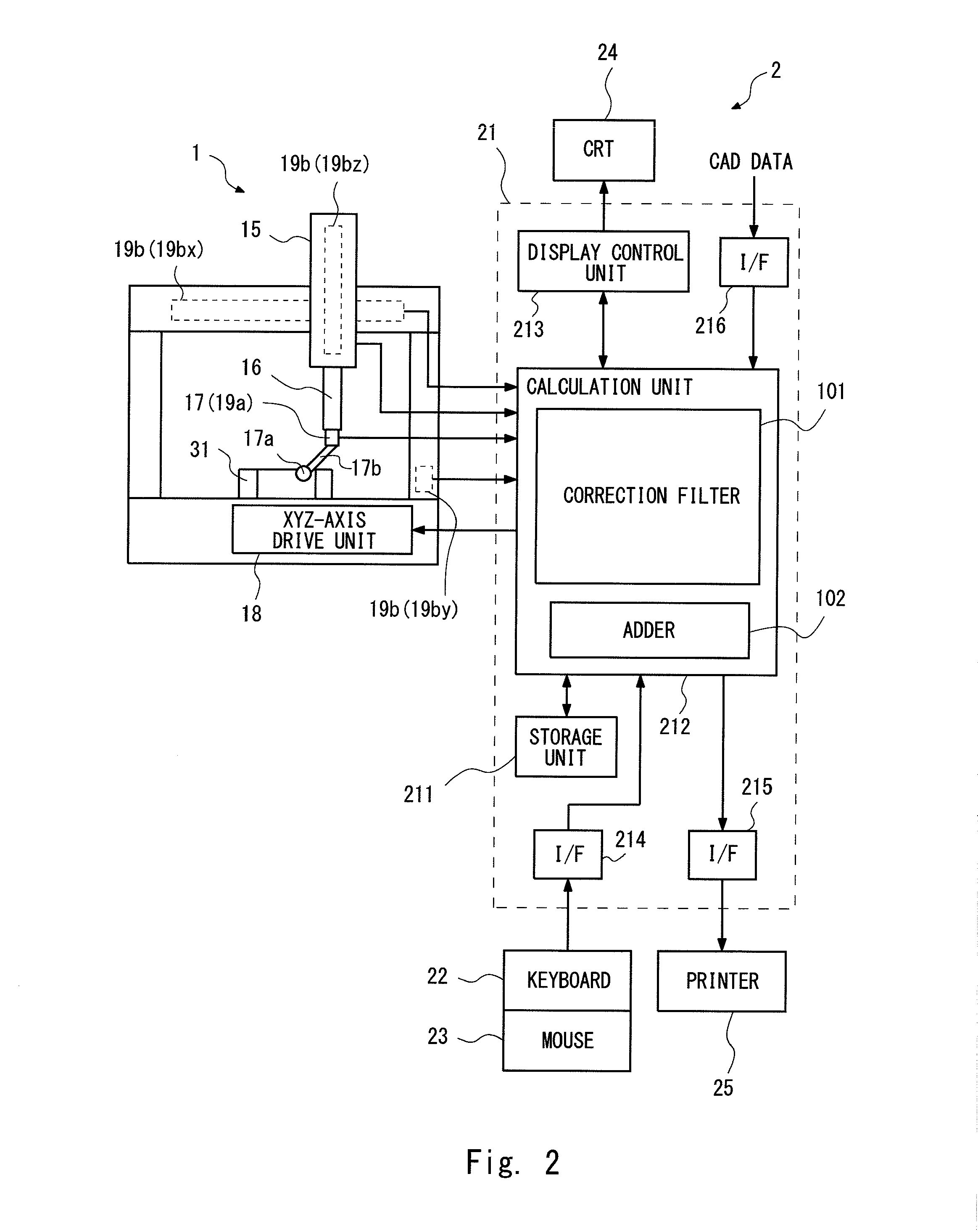
[0064]Next, a shape measuring machine 200 according to a second exemplary embodiment is explained. FIG. 7 is a control block diagram of the calculation unit 222 and its peripheral devices of the shape measuring machine 200 according to the second exemplary embodiment. The configuration of the shape measuring machine 200 is substantially the same as that of the shape measuring machine 100 except that the calculation unit 212 is replaced by a calculation unit 222. The calculation unit 222 includes a correction filter 201 having a similar function to that of the correction filter 101. The correction filter 201 includes a first filter 201a, a second filter 201b, and a third filter 201c. The other configuration of the shape measuring machine 200 is similar to that of the shape measuring machine 100, and therefore its explanation is omitted.

[0065]Next, a measurement value calculation process performed by the shape measuring machine 200 is explained. The shape measuring machine 200 perform...


PUM


Abstract

A shape measuring machine includes a slider that supports a scanning probe including a tip sphere. A scale unit detects a displacement of the slider. A tip sphere displacement detection unit detects a displacement of the tip sphere. A calculation unit includes a correction filter and an adder, and calculates a measurement value from the displacements of the slider and the tip sphere. The correction filter outputs a correction value that is obtained by correcting the displacement of the tip sphere detected by the tip sphere displacement detection unit based on an inverse characteristic of a frequency transfer characteristic from the scale unit to the tip sphere. The adder calculates the measurement value by adding the displacement of the slider detected by the scale unit and the correction value.

Description

INCORPORATION BY REFERENCE[0001]This application is based upon and claims the benefit of priority from Japanese patent application No. 2012-250077, filed on Nov. 14, 2012, the disclosure of which is incorporated herein in its entirety by reference.BACKGROUND OF THE INVENTION[0002]1. Field of the Invention[0003]The present invention relates to a shape measuring machine and a method of correcting a shape measurement error. For example, the present invention relates to a shape measuring machine such as a coordinate measuring machine and a method of correcting an error in its shape measurement.[0004]2. Description of Related Art[0005]These days, shape measuring means such as a coordinate measuring machine is used to inspect the machining accuracy (or processing accuracy) of a product having a 3D (three-dimensional) shape. Such a coordinate measuring machine carries out shape measurement, for example, by moving a scanning probe along a 3D shape.[0006]For example, when measurement using a...

Claims


Application Information

Patent Timeline
IPC IPC(8): G01B5/008
CPCG01B5/008G01B21/045
Inventor ISHIKAWA, NOBUHIRONAKAGAWA, HIDEYUKI
Owner MITUTOYO CORP
Why Eureka
Try Eureka