Display panel control device, liquid crystal display device, electronic apparatus, and display panel drive control device

a control device and liquid crystal display technology, applied in the direction of instruments, computing, electric digital data processing, etc., can solve the problems of reducing the efficiency of luminance, increasing the power consumption for obtaining luminance, and difficult to keep the balance of overall performance, so as to improve the gap in the moving picture and improve the effect of the gap, simple structure and low cos

Active Publication Date: 2012-09-11
HANNSTAR DISPLAY CORPORATION
View PDF8 Cites 9 Cited by
  • Summary
  • Abstract
  • Description
  • Claims
  • Application Information

AI Technical Summary

Benefits of technology

[0039]The present invention has been designed to overcome the various kinds of issues of the above-described techniques. An exemplary object of the invention is to provide a display panel control device, a liquid crystal display device, and the like, which can improve the gap in the moving pictures, ghost-image-like motion blur, and the like with a simple structure without increasing the dividing number of light source blocks.

Problems solved by technology

Thus, the luminance efficiency goes down, so that the power consumption becomes increased for obtaining the luminance that is equivalent to the luminance before employing the black insertion drive.
Therefore, it is difficult to keep the balance of overall performance.
Thus, the contrast in the display becomes deteriorated.
Further, the backlight is always lighted up even in the period of the black display, which results in having poor luminance efficiency.
However, there is a following issue with the scanning backlight drive of Patent Document 1.
That is, since there is a time lag in blinking of each of the backlight light source blocks, light emitted from a given light source block leaks to the other light source block areas.
This causes an imperfect backlight light-off state.
However, as shown in FIG. 57, if there is a light leakage between the light source blocks and light-off state is imperfect, the motion blur of the moving pictures are generated as ghost image.
Thus, the quality of the moving pictures becomes deteriorated than that of the normal drive.
Thus, the light-off state of the backlight becomes insufficient due to the light leakage occurred between the light source blocks.
Therefore, the moving picture is viewed in a duplicated manner as in a case with ghost image, so that a sufficient moving picture improving effect cannot be brought out.
Thus, it is not practical to provide the same number of light emitting areas as the number of scanning lines.
Thus, for the display of the above-described case, eyes of human beings recognize even very small gap in a moving picture of a low speed, so that the picture quality is deteriorated.
This results in increasing the cost.
Therefore, the picture quality is more deteriorated than normal moving picture blurring.
Furthermore, the backlight structure becomes complicated, and the individual variations of the light sources such as the cold cathode tubes (CCFL) turn out directly as luminance unevenness of the divided light source blocks.
Therefore, it is necessary to control the luminance of the light sources of each divided light source block, which results in a large increase in the cost.
Further, as shown in FIG. 64 and FIG. 65, there is such an issue in the light shielding structure that designing thereof is not easy because shadows of the light-shielding walls tend to appear on the screen, even though it is possible to prevent the light leakage.
As a result, as shown in FIG. 72, the colored motion blur generated in the moving picture becomes changed and the picture quality is deteriorated if inexpensive CCFL is used for the light source in the scanning backlight drive.
As described above, the motion blur of the moving picture cannot be improved uniformly on the whole screen only with the scanning backlight drive.

Method used


Image

  • Display panel control device, liquid crystal display device, electronic apparatus, and display panel drive control device
  • Display panel control device, liquid crystal display device, electronic apparatus, and display panel drive control device
  • Display panel control device, liquid crystal display device, electronic apparatus, and display panel drive control device

Examples


first exemplary embodiment

(Overall Structure of Liquid Crystal Display Device)

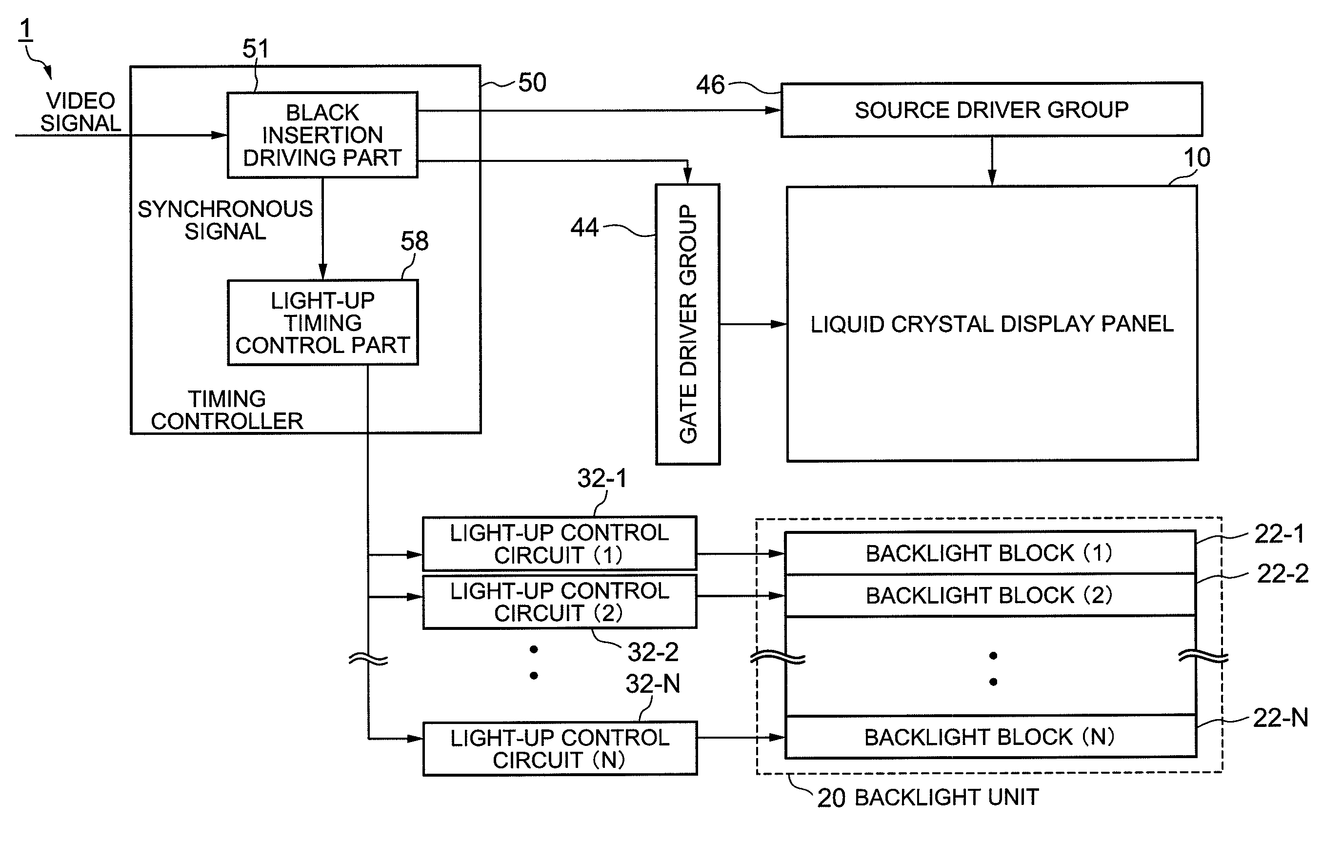
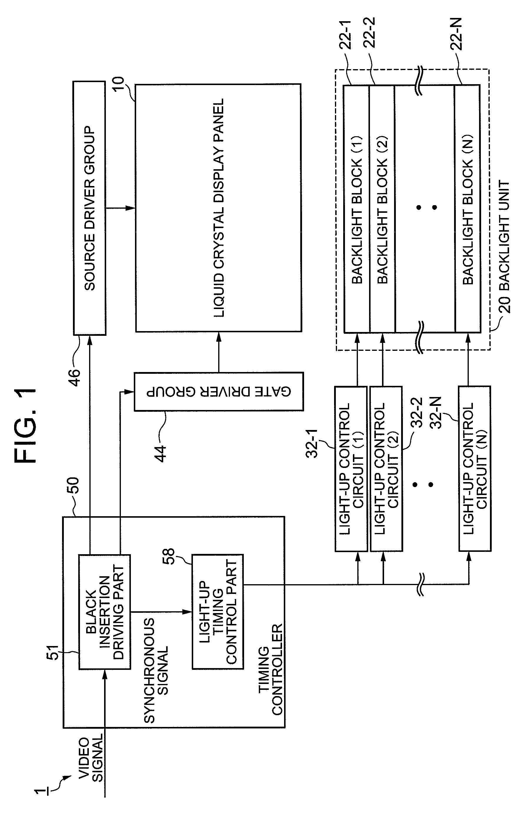
[0123]First, before explaining the structure and operation for performing the invented “scanning backlight drive” that is the feature of this exemplary embodiment, the overall structure of the liquid crystal display device and the structure for performing black insertion drive will be described. FIG. 1 is a block diagram showing an example of an overall schematic structure of the liquid crystal display device according to a first exemplary embodiment of the invention.

[0124]A liquid crystal display device 1 according to this exemplary embodiment is capable of performing black insertion drive and scanning backlight drive. As shown in FIG. 1, the liquid crystal display device 1 is configured, including: a liquid crystal display panel 10; a gate driver group 44 and a source driver group 46 for driving the liquid crystal display panel 10; a backlight unit 20 configured with a plurality (N) of backlight blocks 22 (22-1 to 22-N); N-number...

second exemplary embodiment

[0314]Next, a second exemplary embodiment of the invention will be described by referring to FIG. 39 to FIG. 43. Hereinafter, explanations of substantially the same structures as those of the first exemplary embodiment are omitted, and only the different points are described. FIG. 39 is a block diagram showing an example of the second exemplary embodiment of the liquid crystal display device according to the invention.

[0315]In this exemplary embodiment, black display scanning is performed in one of sub-frame periods out of those obtained by dividing one frame period, and video display scanning is performed in the other sub-frame period.

[0316]Specifically, a liquid crystal display device 300 of this exemplary embodiment is capable of performing double-speed driving. As shown in FIG. 39, the liquid crystal display device 300 is configured, including: a liquid crystal display panel 310 in the same structure as that of the first exemplary embodiment, a gate driver group 344; a source dr...

third exemplary embodiment

[0347]Next, a third exemplary embodiment of the invention will be described by referring to FIG. 44. Hereinafter, explanations of substantially the same structures and the processing procedures as those of the first exemplary embodiment are omitted, and only the different points are described. FIG. 44 is a block diagram showing an example of the third exemplary embodiment in which a liquid crystal display device having the display panel control device of the invention is applied to a broadcast receiving device.

[0348]As shown in FIG. 44, a broadcast receiving device 500 is configured, including a liquid crystal display device 574 that has the same structure as any of the liquid crystal display devices according to the above-described exemplary embodiments.

[0349]The broadcast receiving device 500 is configured, further including: an analog tuner 502 used for terrestrial analog broadcasting; a demodulator 504 which demodulates signals from the analog tuner 502; a digital tuner 512 used...


PUM


Abstract

To provide a display panel control device capable of improving gap of moving pictures, etc., without increasing the dividing number of the backlight. The device includes: a black image insertion driving part which performs, on a display panel, black image insertion drive in which video display scanning and black image display scanning are executed in a specific period; and a light-up timing control part which controls a light-up start timing and a light-off start timing of each light source block based on a synchronous signal which synchronizes with the start timing of the video display scanning or the black image display scanning. The light-off period of the light source block is equal to or less than a period from the end of black image display scanning performed on all display lines within a block area to the start of video scanning performed on the first display line within the area.

Description

CROSS-REFERENCE TO RELATED APPLICATION[0001]This application is based upon and claims the benefit of priority from Japanese patent application No. 2008-092866, filed on Mar. 31, 2008, the disclosure of which is incorporated herein in its entirety by reference.BACKGROUND OF THE INVENTION[0002]1. Field of the Invention[0003]The present invention relates to a display panel control device, a liquid crystal display device, and the like. More specifically, the present invention relates to backlight drive of the liquid crystal display device.[0004]2. Description of the Related Art[0005]In order to improve motion blur generated in moving pictures that are displayed in a hold-type display device such as a liquid crystal display device, there has been proposed for a case of a liquid crystal display panel, for example, to make the display to be of an impulse type in a pseudo manner, such as employing black insertion drive which displays a black signal between image signals at a specific rate, ...

Claims


Application Information

Patent Timeline
Patent Type & Authority Patents(United States)
IPC IPC(8): G09G3/36G06F3/038G09G5/00
CPCG09G3/342G09G3/3648G09G2310/024G09G2310/061
Inventor KIMURA, HIROAKI
Owner HANNSTAR DISPLAY CORPORATION
Why Eureka
Try Eureka