Video communication quality estimation apparatus, method, and program

a video communication and quality estimation technology, applied in the field of communication quality estimation techniques, can solve the problems of affecting the quality of audio information and video information that the user actually feels on the receiving terminal, affecting the quality of user experience of audio information and video information, etc., to achieve the effect of reducing the quality of audio information

Active Publication Date: 2013-03-26
NIPPON TELEGRAPH & TELEPHONE CORP
View PDF9 Cites 301 Cited by
  • Summary
  • Abstract
  • Description
  • Claims
  • Application Information

AI Technical Summary

Benefits of technology

[0018]According to the present invention, the multi-modal quality estimation unit estimates a multi-modal quality value on the basis of an audio quality evaluation value and a video quality evaluation value, and the delay quality degradation amount estimation unit estimates a delay quality degradation amount on the basis of an audio delay time and a video delay time. The video communication quality estimation unit estimates a video communication quality value on the basis of the multi-modal quality value and the delay quality degradation amount. This makes it possible to estimate a video communication quality value in consideration of quality degradation due to the delays of audio and video media, and hence to estimate, with sufficient accuracy, quality associated with video communication of bidirectionally exchanging audio and video media upon compositing them.

Problems solved by technology

The Internet used for such services is a network which does not always guarantee the communication quality.
For this reason, in communicating audio and video media upon compositing them, if the operating band of a communication line connecting user terminals is narrow or congestion occurs in the network, the quality of user experience of audio information and video information which the user actually feels on the receiving terminal degrades.
More specifically, the occurrence of quality degradation in audio information is perceived as breaks, noise, and a response delay, and the occurrence of quality degradation in video information is perceived as phenomena such as defocus, blur, mosaic-shaped distortion, jerky effect, and a response delay.
In some cases, a user perceives a response delay caused by the synchronization between audio and video media, i.e., a video communication service response delay, the step-out between audio and video media which is caused by a response time delay offset, or the like due to the processing time taken for the transmission of audio and video media signals, a delay time in the network, and a delay time originating from the processing time taken for the reception of audio and video media signals.

Method used


Image

  • Video communication quality estimation apparatus, method, and program
  • Video communication quality estimation apparatus, method, and program
  • Video communication quality estimation apparatus, method, and program

Examples


first embodiment

[Operation of First Embodiment]

[0073]The operation of the video communication quality estimation apparatus according to the first embodiment of the present invention will be described next in detail.

[Overall Processing Operation]

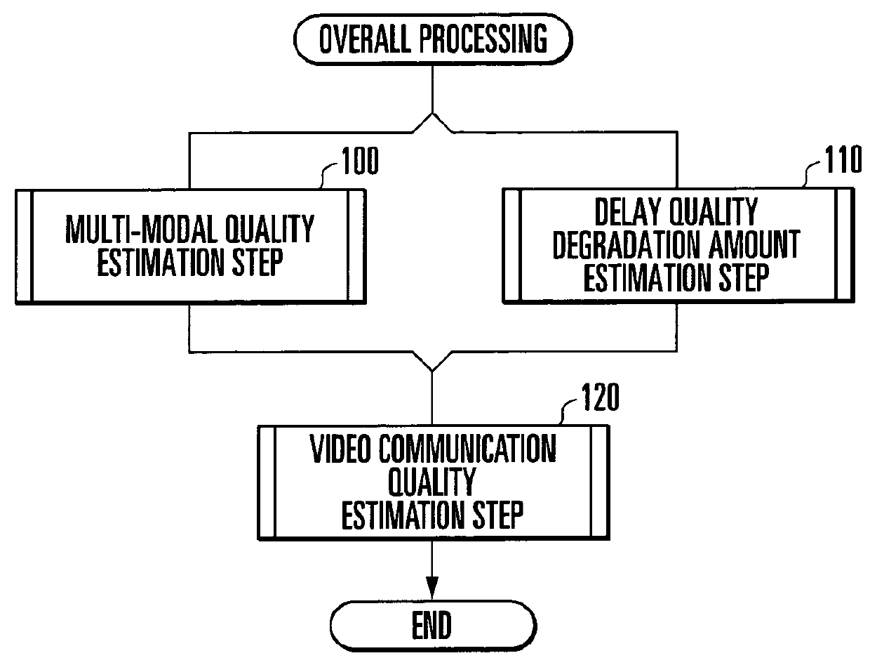
[0074]The video communication quality estimation operation of the video communication quality estimation apparatus according to the first embodiment of the present invention will be described first with reference to FIG. 2. FIG. 2 is a flowchart showing the overall processing operation of the video communication quality estimation apparatus according to the first embodiment of the present invention.

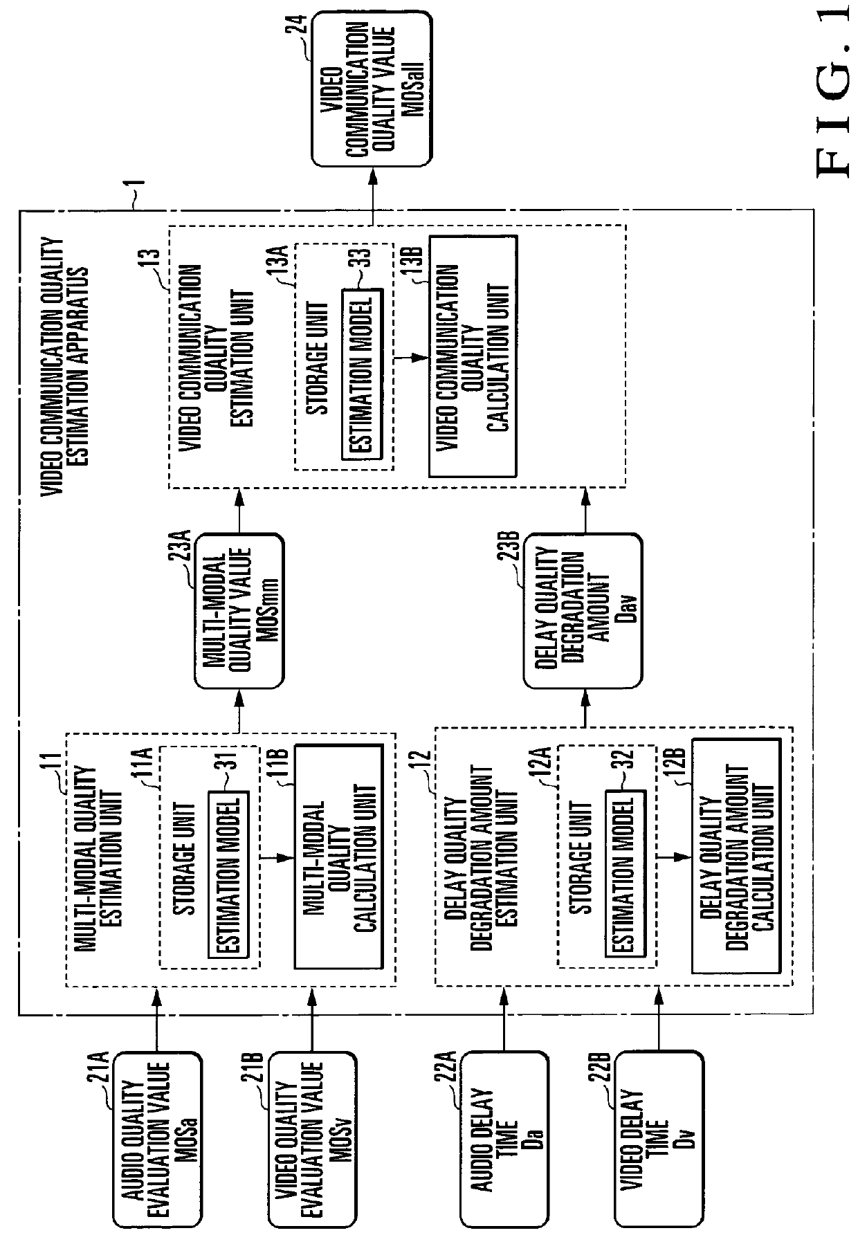
[0075]Assume that the audio quality evaluation value 21A, video quality evaluation value 21B, audio delay time 22A, and video delay time 22B have been input as pieces of quality information about an arbitrary video communication performed between communication terminals from an external apparatus, storage medium, communication network, or keyboard (not shown). A c...

second embodiment

[Operation of Second Embodiment]

[0123]Of the operations performed by the video communication quality estimation apparatus according to the second embodiment of the present invention, the delay quality degradation amount estimation operation will be described in detail next with reference to FIG. 11. FIG. 11 is a flowchart showing delay quality degradation amount estimation processing by the video communication quality estimation apparatus according to the second embodiment of the present invention. The operations of the video communication quality estimation apparatus 1 according to this embodiment differ from those according to the first embodiment in only delay quality degradation amount estimation operation. Other processing operations are the same as those of the first embodiment, and hence a detailed description thereof will be omitted.

[0124]The delay quality degradation amount estimation unit 12 of the video communication quality estimation apparatus 1 executes the delay quali...

third embodiment

[Operation of Third Embodiment]

[0154]Of the operations performed by the video communication quality estimation apparatus according to the third embodiment of the present invention, the delay quality degradation amount estimation operation will be described in detail next with reference to FIG. 16. FIG. 16 is a flowchart showing delay quality degradation amount estimation processing by the video communication quality estimation apparatus according to the third embodiment of the present invention. The operation of the video communication quality estimation apparatus 1 according to this embodiment differs from that according to the second embodiment only in delay quality degradation amount estimation operation. Other processing operations are the same as those of the second embodiment, and a detailed description thereof will be omitted.

[0155]The delay quality degradation amount estimation unit 12 of the video communication quality estimation apparatus 1 executes the delay quality degra...


PUM


Abstract

A multi-modal quality estimation unit (11) estimates a multi-modal quality value (23A) on the basis of an audio quality evaluation value (21A) and a video quality evaluation value (21). In addition, a delay quality degradation amount estimation unit (12) estimates a delay quality degradation amount (23B) on the basis of an audio delay time (22A) and a video delay time (22B). A video communication quality estimation unit (13) estimates a video communication quality value (24) on the basis of a multi-modal quality value (23A) and a delay quality degradation amount (23B).

Description

[0001]The present patent application is a non-provisional application of International Application No. PCT / JP2006 / 317637, filed Sep. 6, 2006.TECHNICAL FIELD[0002]The present invention relates to a communication quality estimation technique and, more particularly, to a technique of estimating quality associated with video communication of bidirectionally exchanging audio and video media upon compositing them.BACKGROUND ART[0003]With advances in high-speed and broadband access lines to the Internet, attention has been paid to bidirectional multi-modal services based on the composition of audio and video media such as video communication services, e.g., video telephone / conference services, and collaboration services.[0004]The Internet used for such services is a network which does not always guarantee the communication quality. For this reason, in communicating audio and video media upon compositing them, if the operating band of a communication line connecting user terminals is narrow...

Claims


Application Information

Patent Timeline
Patent Type & Authority Patents(United States)
IPC IPC(8): H04N7/14H04N9/475
CPCH04N17/004H04N5/04H04N17/00
Inventor HAYASHI, TAKANORIYAMAGISHI, KAZUHISA
Owner NIPPON TELEGRAPH & TELEPHONE CORP
Why Eureka
Try Eureka