Display device with lens array or parallax barrier that switches between narrow view mode and wide view mode

a display device and parallax technology, applied in the field of display devices, can solve the problems of awkwardness of the displayed image, the size of the pixel , the inability to view the displayed information by other people, and achieve the effect of preventing the luminance of the displayed image from being lowered and preventing non-display areas (dark areas)

Active Publication Date: 2013-09-03
NEC LCD TECH CORP
View PDF12 Cites 7 Cited by
  • Summary
  • Abstract
  • Description
  • Claims
  • Application Information

AI Technical Summary

Benefits of technology

[0012]It is an exemplary object of the present invention to provide a display device which is capable of preventing the luminance of a displayed image from being lowered when the display device displays an image in a narrow view range, and which is capable of preventing non-display areas (dark areas) from being created when the display device displays an image in a wide view range.

Problems solved by technology

On the other hand, there is a situation where the displayed information should not be viewed by other people.
Firstly, the size of view range 105 is determined by the size of pixel 103. Therefore, if the view range is to be set to a narrow range, then the size of pixel 103 needs to be reduced, and the display device displays images with a low luminance level, i.e., dark images.
Secondly, there is a non-display area created between view range 105 and view range 106 or 107 because the gap between pixels 103, 104 is magnified by the lens. As a result, the viewer sees dark lines in the displayed image, and feels awkward about the displayed image. The darks lines are caused when both pixels 103, 104 are displayed in order to display an image in a wide view angle. As the viewer has to attempt to view the image while avoiding the dark lines, the display device, in practice, fails to provide wide view angles.

Method used


Image

  • Display device with lens array or parallax barrier that switches between narrow view mode and wide view mode
  • Display device with lens array or parallax barrier that switches between narrow view mode and wide view mode
  • Display device with lens array or parallax barrier that switches between narrow view mode and wide view mode

Examples


1st example

[0053]A display device according to a first example of the present invention will be described below with reference to FIGS. 8 through 11.

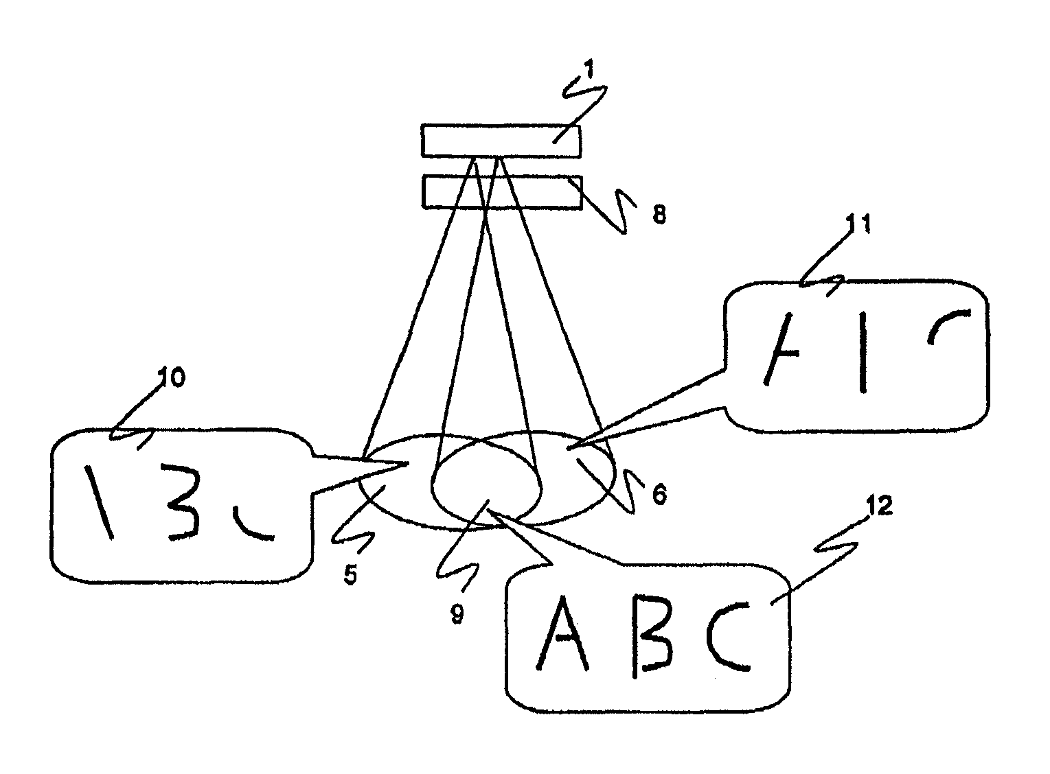
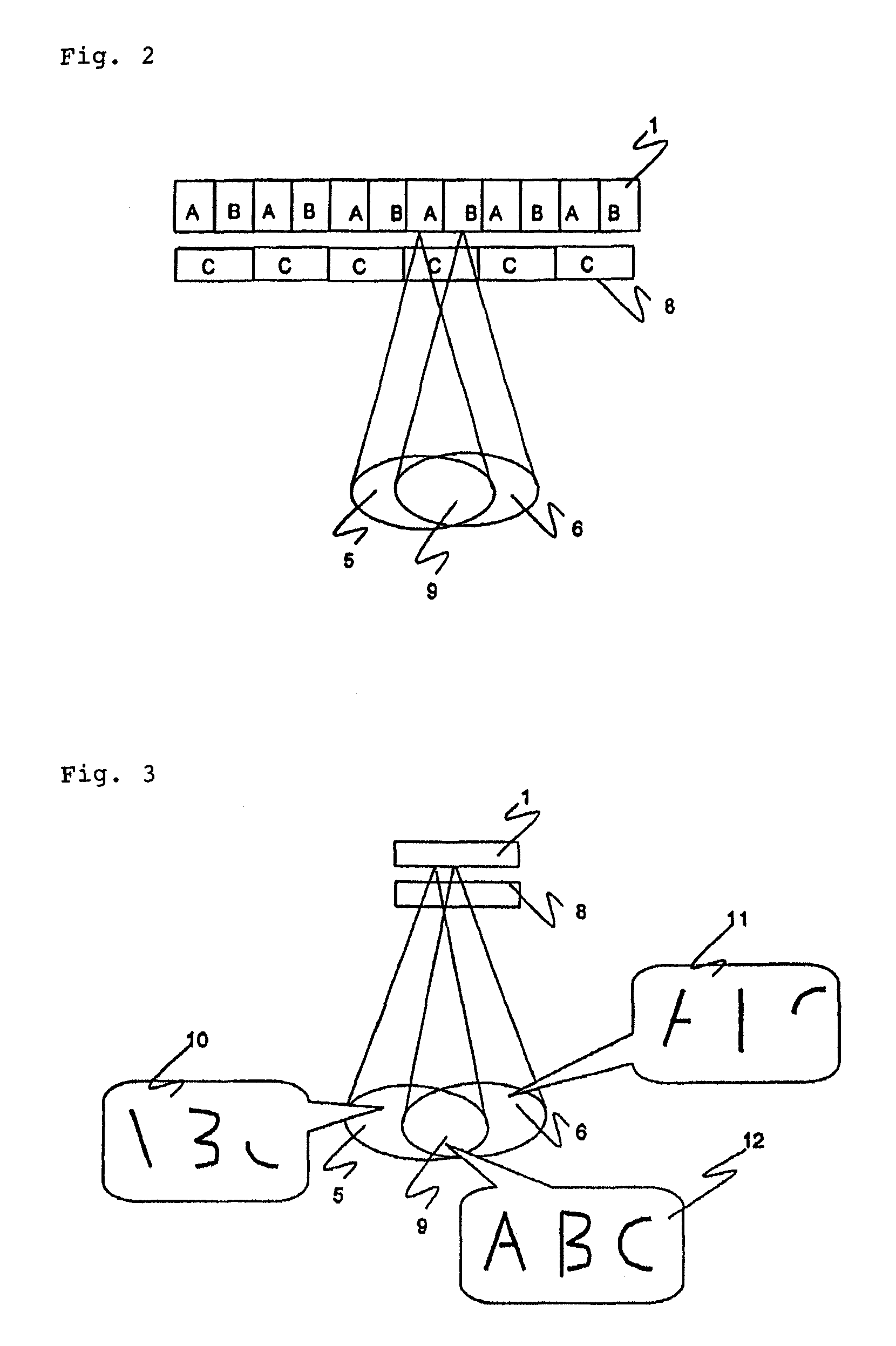
[0054]As shown in FIG. 8, the display device according to the first example comprises display panel 24 and parallax barrier 23 disposed on display panel 24. Parallax barrier 23 serves as a multiple viewpoint activating means. Display panel 24 may comprise a liquid crystal display panel or a light emission display panel. Parallax barrier 24 comprises an alternate array of light-impermeable strips and light-permeable strips which are arranged such that each of the strips is oriented in the vertical direction of display panel 24.

[0055]Display panel 24 comprises a plurality of pixel groups of two types, i.e., pixel groups A, B. Pixel groups A and Pixel groups B are alternately arranged in an array along the horizontal direction of display panel 24. The layout of both pixel groups A, B is illustrated in FIG. 8. As shown in FIG. 8, only an image display...

2nd example

[0059]A display device according to a second example of the present invention will be described below with reference to FIGS. 12 and 13.

[0060]The display device according to the second example includes liquid crystal device 32 as a multiple viewpoint activating means. As shown in FIG. 12, the display device comprises display panel 24 and a parallax barrier disposed in front of display panel 24 and comprising liquid crystal device 32.

[0061]The parallax barrier in the form of liquid crystal device 32 comprises first substrate 31a positioned opposite display panel 24 and second substrate 31b positioned opposite first substrate 31a. Each of first and second substrates 31a, 31b is made of glass or plastic. Polarizer 28 is mounted on the surface of first substrate 31a which faces display panel 24. Another polarizer 28 is mounted on the surface of second substrate 31b which is remote from first substrate 31a. First transparent electrode 29a is mounted on the surface of first substrate 31a ...

3rd example

[0067]A display device according to a third example of the present invention will be described below with reference to FIGS. 14 through 16.

[0068]The display device according to the third example includes a voltage-controllable lens array device as a multiple viewpoint activator. As shown in FIG. 14, the voltage-controllable lens array device comprises first substrate 31a and second substrate 31b disposed opposite first substrate 31a. First transparent electrode 29a is mounted on the surface of first substrate 31a which faces second substrate 31b. Second transparent electrode 29b is mounted on the surface of second substrate 31b which faces first substrate 31a. First transparent electrode 29a is disposed substantially fully over first substrate 31a. Second transparent electrode 29b comprises a plurality of strips. Two liquid layers, i.e., first liquid 37 and second liquid 38, are sealed between first substrate 31a and second substrate 31b. Liquids 37, 38 are insoluble into each other...


PUM


Abstract

A display device includes a display panel including a plurality of pixel groups for displaying respective images independently of each other, and a parallax barrier for limiting view ranges of images displayed respectively by the pixel groups such that the view ranges overlap each other in an overlap area. The display device is selectively operable in a first display mode in which a significant image is recognizable when images displayed respectively by the pixel groups are simultaneously observed in the overlap area, and in which a significant image is unrecognizable when the images displayed respectively by the pixel groups are observed individually in the view ranges except for the overlap area, respectively, and a second display mode in which a significant image is recognizable both when the images displayed respectively by the pixel groups are simultaneously observed in the overlap area and when the images displayed respectively by the pixel groups are observed individually in the view ranges except for the overlap area, respectively.

Description

BACKGROUND OF THE INVENTION[0001]1. Field of the Invention[0002]The present invention relates to a display device, and more particularly to a display device which is capable of changing a view angle range.[0003]2. Description of the Related Art[0004]With the development of display technology in recent years, display devices that can be viewed in a wide angle range have been put to practical use. Portable information terminals incorporating display devices such as liquid crystal displays have also been in widespread use. If the information displayed on a portable information terminal is to be viewed by a plurality of people, then it is desirable that the information be visible in a wide angle. On the other hand, there is a situation where the displayed information should not be viewed by other people. Consequently, there is a demand for display devices capable of switching between a wide view angle range and a narrow view angle range for viewing the information displayed on the displ...

Claims


Application Information

Patent Timeline
Patent Type & Authority Patents(United States)
IPC IPC(8): G09G5/00
CPCG09G5/00G09G2340/0407
Inventor SUMIYOSHI, KEN
Owner NEC LCD TECH CORP
Why Eureka
Try Eureka