Optical fiber connector

a technology of optical fiber and connector, applied in the field of connectors, can solve the problems of easy evaporation of matching liquid, inconvenient joining of optical fiber stub and field optical fiber,

Active Publication Date: 2015-07-14
HONG FU JIN PRECISION IND (SHENZHEN) CO LTD +1
View PDF15 Cites 3 Cited by
  • Summary
  • Abstract
  • Description
  • Claims
  • Application Information

AI Technical Summary

Benefits of technology

[0005]Fiber To The Home (FTTH) is widely used in communications field, and many optical fiber connectors are needed for connecting the optical fiber. An optical fiber connector generally includes an optical ferrule with an optical fiber stub already terminated in the optical ferrule, an optical fiber holder, and a clamp sleeve sleeved on the optical fiber holder to fasten a field optical fiber. To improve the quality of optical coupling and minimize Fresnel losses of the optical fiber connector, there are two manners of treating a joint between the optical fiber stub and the field optical fiber. In a first manner, a matching liquid is injected in the optical fiber holder. However, the matching liquid evaporates easily. In a second manner, the optical fiber stub and the field optical fiber are joined together by melting them together. However, it is not convenient to precisely join the optical fiber stub and the field optical fiber together.

Problems solved by technology

However, the matching liquid evaporates easily.
However, it is not convenient to precisely join the optical fiber stub and the field optical fiber together.

Method used


Image

  • Optical fiber connector
  • Optical fiber connector
  • Optical fiber connector

Examples


Embodiment Construction

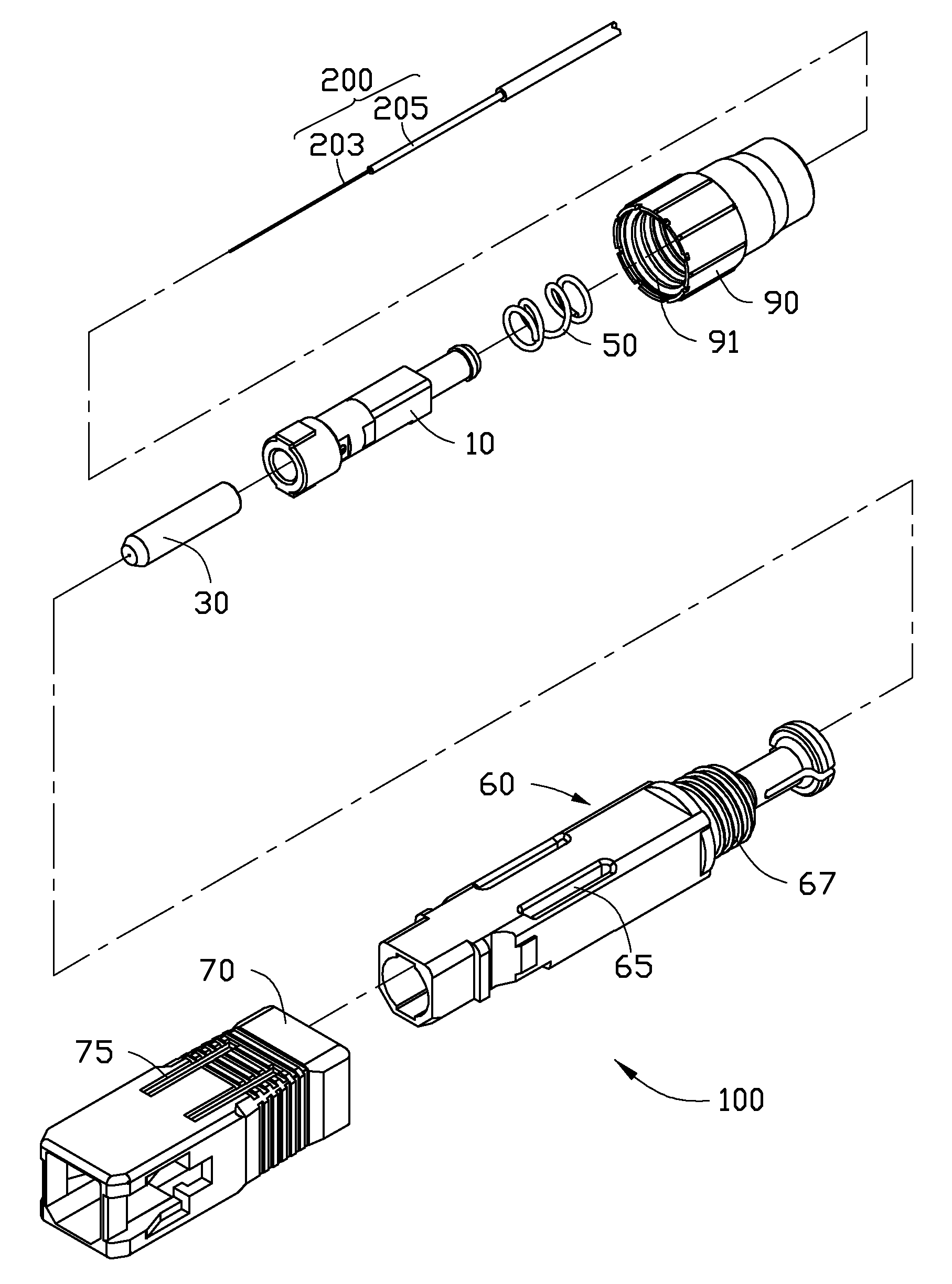
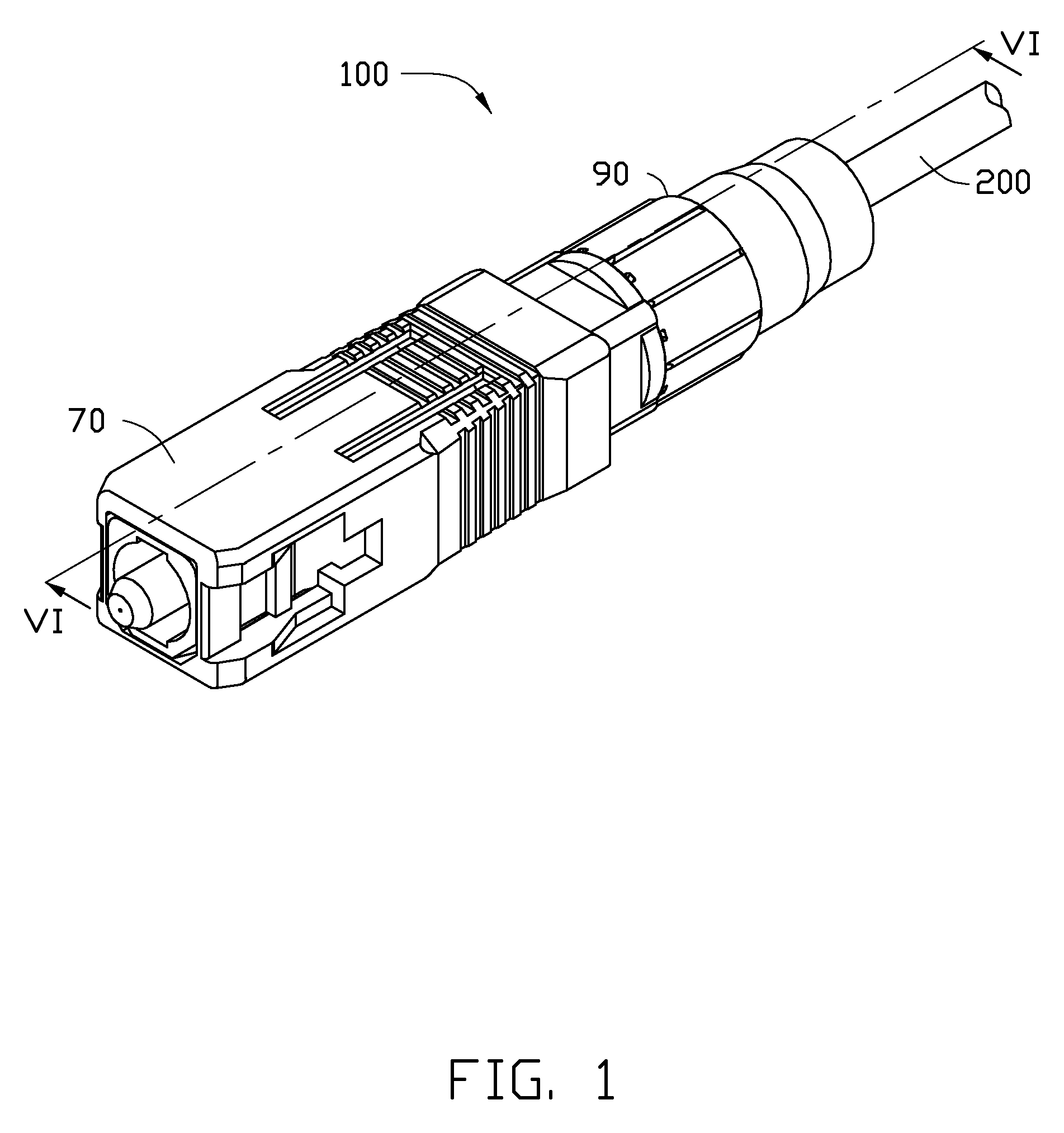
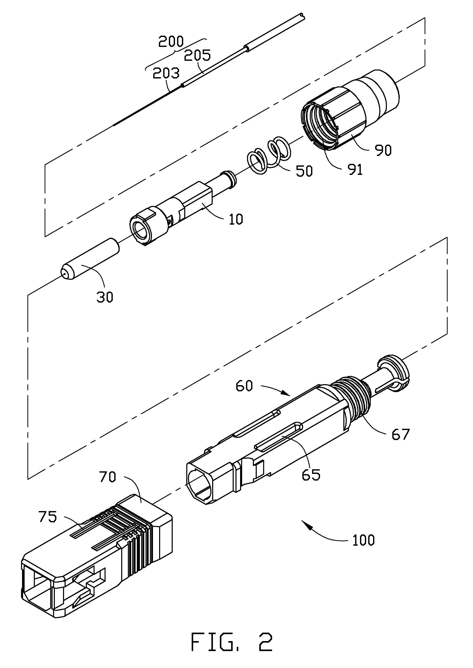
[0019]FIGS. 1 and 2 show an embodiment of an optical fiber connector 100 for gripping a cable 200. The optical fiber connector 100 includes a fixing module 10, an optical fiber ferrule 30, an elastic member 50, an inner housing 60, an outer housing 70, and a boot 90. The optical fiber ferrule 30 is positioned to one end of the fixing module 10. The elastic member 50 is sleeved on the other end of the fixing module 10 away from the optical fiber ferrule 30. The inner housing 60 is sleeved on the fixing module 10. The outer housing 70 is sleeved on the inner housing 60. The boot 90 is sleeved on an end of the inner housing 60 away from the outer housing 70. In the illustrated embodiment, the optical fiber connector 100 is a Subscriber Connector (SC) optical fiber connector. The cable 200 includes an optical fiber 203 and a coating 205 formed on the optical fiber 203. In order to facilitate the cable 200 being gripped in the optical fiber connector 100, part of the coating 205 are remo...


PUM


Abstract

An optical fiber connector includes a fixing module and an optical fiber ferrule positioned at an end of the fixing module. The optical fiber connector is used for gripping a cable including an optical fiber. The optical fiber ferrule axially defines a through hole, the optical fiber is gripped in the fixing module and is partly protruded out of the optical ferrule. When the optical fiber connector is assembled to an adapter to join with another optical fiber connector, the optical fiber will be bent to elastically resist an optical fiber of the another optical fiber connector.

Description

CROSS-REFERENCE TO RELATED APPLICATIONS[0001]This application claims all benefits accruing under 35 U.S.C. §119 from China Patent Application No. 201210100942.8, filed on Apr. 9, 2012, in the China Intellectual Property Office, the disclosure of which is incorporated herein by reference. The application is also related to co-pending applications entitled, “OPTICAL FIBER CONNECTOR AND ASSEMBLING DEVICE FOR THE SAME” Ser. No. 13 / 792,215; “FIBER END SURFACE MACHINING DEVICE AND FIBER POSITION STRUCTURE THEREOF” Ser. No. 13 / 792,218; “FIBER MACHINING DEVICE AND ASSEMBLING METHOD FOR OPTICAL FIBER CONNECTOR”Ser. No. 13 / 792,219; “OPTICAL FIBER CONNECTOR” Ser. No. 13 / 792,222; “OPTICAL FIBER CONNECTOR” Ser No. 13 / 792,223; “OPTICAL FIBER CLAMPING MECHANISM AND OPTICAL FIBER CONNECTOR USING THE SAME” Ser. No. 13 / 792,229.BACKGROUND[0002]1. Technical Field[0003]The present disclosure relates to connectors, particularly to an optical fiber connector.[0004]2. Description of the Related Art[0005]Fi...

Claims


Application Information

Patent Timeline
Patent Type & Authority Patents(United States)
IPC IPC(8): G02B6/38G02B6/36G02B6/255
CPCG02B6/381G02B6/36G02B6/3858G02B6/3869G02B6/2552G02B6/3823G02B6/3887G02B6/3898G02B6/3888
Inventor LI, ZHI-MINGWEI, LE-PENG
Owner HONG FU JIN PRECISION IND (SHENZHEN) CO LTD
Why Eureka
Try Eureka