Supercharge Your Innovation With Domain-Expert AI Agents!

Spinning reel and spinning reel spool

a spinning reel and spool technology, applied in the field of spinning reels, can solve the problems of abutting member deformation or breakage of the abutting member, spool body may corrode from the effect of foreign substances, and the durability of the spool body may degrade, so as to achieve the effect of reducing the durability of the spool body

Active Publication Date: 2016-01-05
SHIMANO INC
View PDF10 Cites 0 Cited by
  • Summary
  • Abstract
  • Description
  • Claims
  • Application Information

AI Technical Summary

Benefits of technology

[0008]The present invention was made with consideration given to the problems described above, and the object of the present invention is to enhance the durability of the spool.
[0028]According to the present invention, the durability of the spinning reel spool can be enhanced.

Problems solved by technology

Therefore, once a foreign substance such as seawater or the like infiltrates this closed space, there is a concern that the spool body may corrode from the effect of the foreign substance.
Namely, there is a concern that the durability of the spool body may degrade.
Therefore, if the abutting member is formed from a resin or the like to achieve reduction in the weight of the spool, there is a concern, depending on the material that was selected, that the abutting member may be deformed or broken by the stress generated in the abutting member.

Method used


Image

  • Spinning reel and spinning reel spool
  • Spinning reel and spinning reel spool
  • Spinning reel and spinning reel spool

Examples


first embodiment

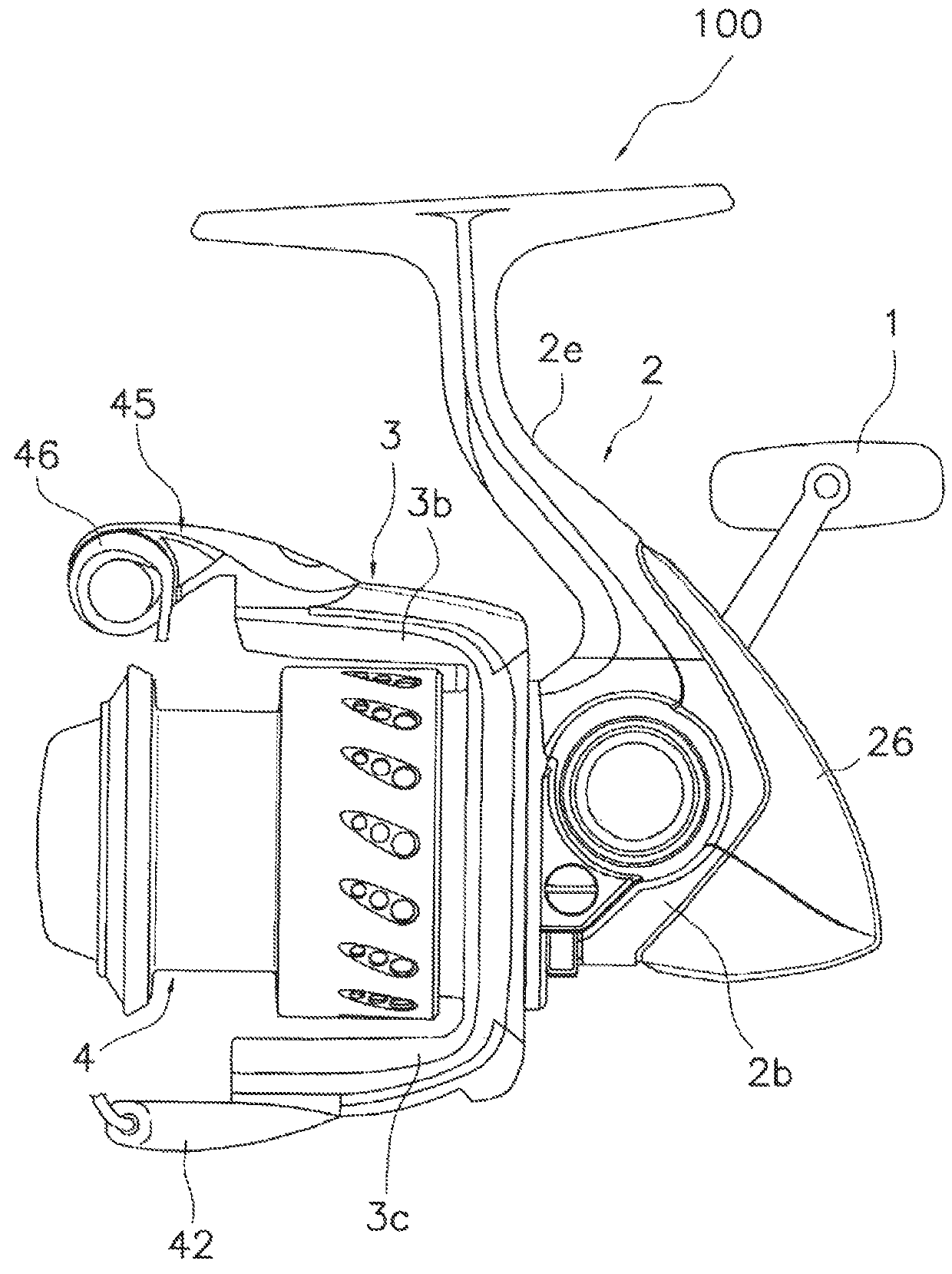
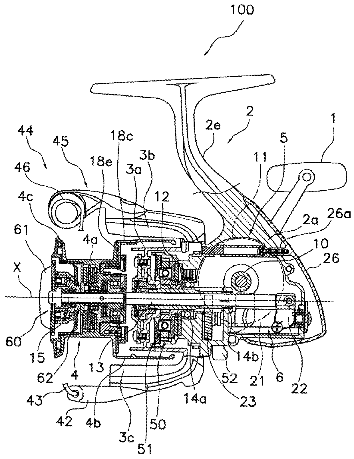
[0043]As illustrated in FIG. 1, the spinning reel 100 according to the first embodiment of the present invention is a reel capable of delivering fishing line forward. As illustrated in FIGS. 1 and 2, the spinning reel 100 basically comprises a handle 1, a reel body 2, a rotor 3, and a spinning reel spool 4. The handle I is rotatably mounted to the reel body 2. The handle 1 can be mounted on either the right side or the left side of the reel body 2.

[0044]As seen in FIG. 2, the reel body 2 includes a housing portion 2a, a lid member 2b and a guard member 26. The housing portion 2a has an opening at one side portion. The lid member 2b covers the opening at the side portion of the housing portion 2a. The guard member 26 is mounted to the rear portion of the housing portion 2a. The reel body 2 further includes a T-shaped fishing rod mounting portion 2e that extends in the longitudinal direction. The T-shaped fishing rod mounting portion 2e is integrally formed on the top portion of the h...

second embodiment

[0079]The spinning reel 200 according to the second embodiment in the present invention is a reel that can deliver fishing line in the forward direction. The spinning reel 200 according to the second embodiment has the same configuration as that of the spinning reel 100 described in the first embodiment except for the configuration of the spool 104. Therefore, the description of the configuration that is the same as that of the spinning reel 100 in the first embodiment will be omitted. Only the configuration that varies from the spinning reel 100 in the first embodiment will be described. Refer to the description in the first embodiment for sections where the description has been omitted.

[0080]As illustrated in FIG. 6, the spool 104 is for winding fishing line on its outer circumferential surface and is disposed at the front portion of the rotor 103 to move in the longitudinal direction. The spool 104 includes a spool body 141, a ring member 108, a fastening member 109, and a coupli...


PUM


Abstract

A spinning reel spool according to a first aspect of the present invention is a spinning reel spool that delivers fishing line forward. The spinning reel spool comprises a spool body and a ring member. This spool body has a body portion and a protruding portion. The protruding portion is integrally formed on a front side of the body portion. The protruding portion is annularly arranged and protrudes from the body portion in an axial direction of the spool body. The ring member is disposed on an outer circumferential portion of the protruding portion of the spool body. The ring member is held between the body portion and a plastically deformed part of the protruding portion.

Description

CROSS-REFERENCE TO RELATED APPLICATIONS[0001]This application claims priority to Japanese Patent Application No. 2012-277878, filed on Dec. 20, 2012. The entire disclosure of Japanese Patent Application No. 2012-277878 is hereby incorporated herein by reference.BACKGROUND[0002]1. Field of the Invention[0003]The present invention relates to a spinning reel that delivers fishing line forward and a spool of a spinning reel.[0004]2. Background Information[0005]The conventional spinning reel comprises a spool body, an abutting member (a spool collar), and a ring member (a spool ring). In this type of spinning reel, the ring member is held between the abutting member and the spool body. Specifically, the ring member is held between the abutting member and the spool body by mounting the abutting member to the spool body in a state of having disposed the ring member on the front side of the spool body. See, for example, Japanese Laid-open Patent Publication No. 2008-283931.SUMMARY[0006]In t...

Claims


Application Information

Patent Timeline
Patent Type & Authority Patents(United States)
IPC IPC(8): A01K89/01
CPCA01K89/0111A01K89/01A01K89/027
Inventor HIRAOKA, HIROKAZUTAKAMATSU, TAKUJIKITAJIMA, KEIGOOCHIAI, KOUJISATO, AKIHIKO
Owner SHIMANO INC
Features
  • R&D
  • Intellectual Property
  • Life Sciences
  • Materials
  • Tech Scout
  • Unparalleled Data Quality
  • Higher Quality Content
  • 60% Fewer Hallucinations
Learn More