
Image capturing apparatus, external device, image capturing system, method for controlling image capturing apparatus, method for controlling external device, method for controlling image capturing system, and program
a technology for image capture and external devices, which is applied in the field of image capture apparatuses, external devices, image capture systems, etc., can solve the problems of time delay and difficulty in moving the image capture direction of the network camera by a minute amount, and achieve the effect of convenient and reliable stopping an image capture uni
- Summary
- Abstract
- Description
- Claims
- Application Information
AI Technical Summary
Benefits of technology
Problems solved by technology
Method used
Image



Examples
first embodiment
[0043]Referring to FIG. 1, examples of the hardware configurations of a network camera 1000 and a client device 2000 according to a first embodiment will be described. The network camera 1000 in FIG. 1 is connected to the client device 2000 through a network 3000 (via a network) so as to communicate with each other.
[0044]The network camera 1000 of this embodiment corresponds to a monitoring camera that captures a moving image for use in monitoring. The client device 2000 of this embodiment is an example of an external device. The network camera 1000 and the client device 2000 of this embodiment constitute an image capturing system (a monitoring system).
[0045]The network camera 1000 in FIG. 1 includes an image capturing unit 1001. The image capturing unit 1001 includes lenses, such as a focus lens and a zoom lens (not shown), and an image sensor, such as a CCD or a CMOS.
[0046]The image capturing unit 1001 generates an analog signal by capturing an image of a subject formed with the l...
second embodiment
[0220]Subsequently, referring to FIGS. 11A and 11B and FIG. 12, a second embodiment of the present invention will be described. The same components as those in the first embodiment are given the same reference numerals, and descriptions thereof may be omitted.
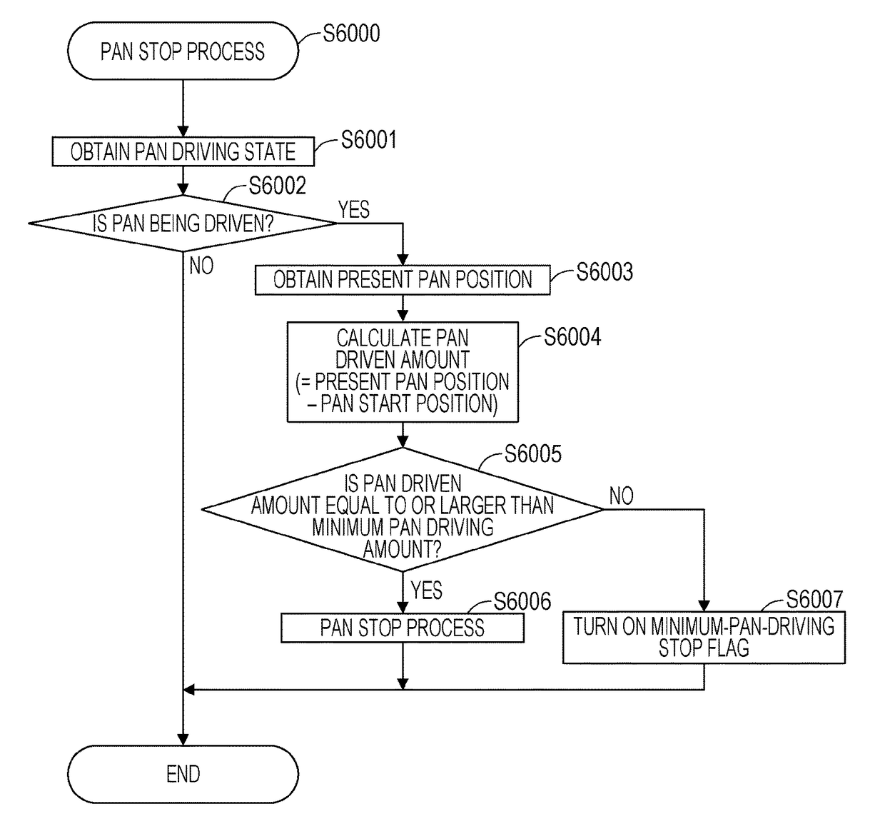
[0221]In the network camera 1000 of the first embodiment, the pan driving unit 1006 (the tilt driving unit 1007) has a minimum pan driving amount (a minimum tilt driving amount). Furthermore, even if a pan (tilt) stop command is received directly after a direction-designating moving command is received by the communication unit 1009, the pan driving unit 1006 (the tilt driving unit 1007) stops after certainly driving by a minimum pan driving amount (a minimum tilt driving amount).
[0222]In contrast, the network camera 1000 of the second embodiment differs in that the minimum pan driving amount (the minimum tilt driving amount) can be set by the client device 2000 (that is, a user who operates the client device 2000). This allows...
third embodiment
[0247]Subsequently, a third embodiment of the present invention will be described with reference to FIGS. 13A to 13C and FIG. 14. The same components as those in the above embodiments are given the same reference signs, and descriptions thereof may be omitted.
[0248]In the second embodiment, a method for designating a minimum pan driving amount (a minimum tilt driving amount) of the pan driving unit 1006 (the tilt driving unit 1007) of the network camera 1000 with the client device 2000 (that is, the user).
[0249]In contrast, the network camera 1000 of the third embodiment transmits information indicating whether the minimum pan driving amount (the minimum tilt driving amount) of the pan driving unit 1006 (the tilt driving unit 1007) can be set from the client device 2000 to the client device 2000. This makes it easier to reflect user's intention to the operability of the network camera 1000 in the image capture direction. The third embodiment with consideration given to the above poi...
PUM
 Abstract
Description
Claims
Application Information