
Improved structure of drafting device in ribbon lap machine
A technology of drafting device and winding machine, which is applied in the direction of drafting equipment, spinning machines, textiles and papermaking, etc. It can solve the problems of complex drafting structure of sliver and lapping machine, achieve improved drafting effect, simple mechanism and convenient The effect of working parameters
Patent Information
- Authority / Receiving Office
- CN · China
- Current Assignee / Owner
- Publication Date
- 2010-09-01
- Estimated Expiration
- Not applicable · inactive patent
Smart Images
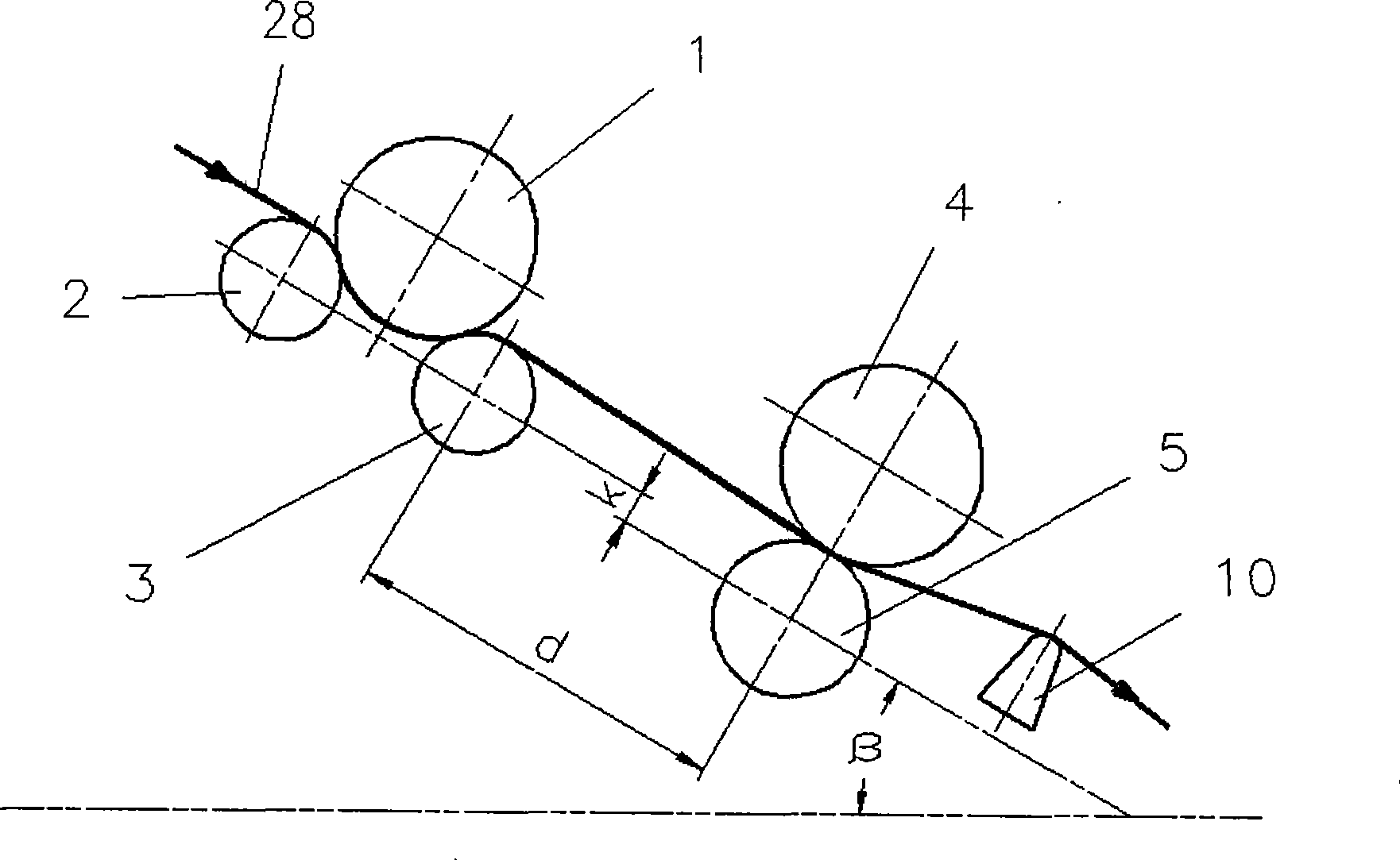
Figure 1 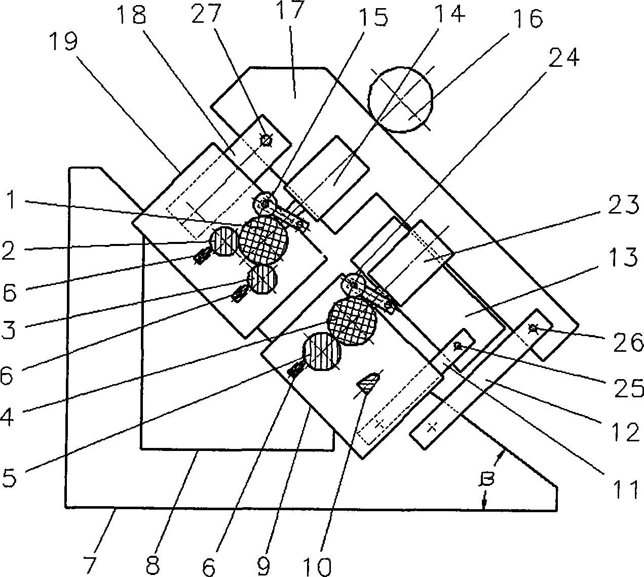
Figure 2 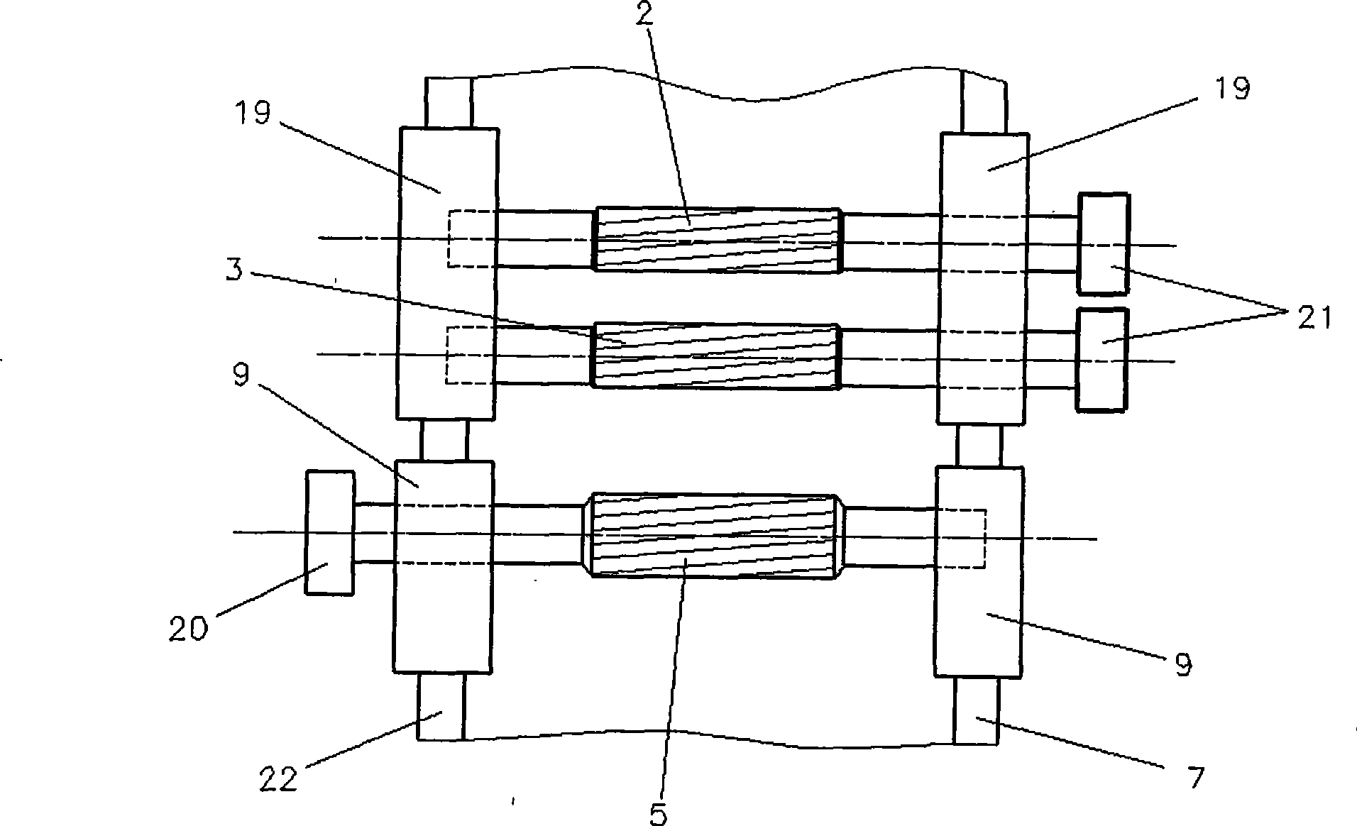
Figure 3
Abstract
Description
Technical field:
[0001] The invention relates to the field of machinery, in particular to textile machinery, in particular to a sliver doubling machine, and in particular to an improved structure of a drafting device in the sliver doubling machine. Background technique:
[0002] In the prior art, the sliver doubling machine adopts a drafting pattern of four up and four down, or three up and three down, or two up and three down. The four-up and four-down drafting structure is composed of four rubber rollers of the same diameter and four metal grooved rollers of the same diameter. There are three drafting areas. The drafting device has an included angle with the horizontal, and is composed of a support plate on one side. The flip angle of the support and opening device is less than 90°, and the air bag is used to realize the drafting and pressurization. The pressure of each rubber roller is the same, and the metal groove roller is driven by a gear box. The whole mechanism is r...
Examples
Embodiment Construction
[0024] Such as figure 1 , figure 2 , image 3 and Figure 4 As shown, the improved structure of the drafting device in a sliver doubling machine of the present invention is composed of a support plate 7 and a support plate 22, and the support plate 7 and the support plate 22 are arranged in parallel and at intervals, wherein the support plate 7 and the support plate 22 are all in the form of Right-angled triangle, a connecting rod (not shown) is arranged between the support plate 7 and the support plate 22, and a first roller seat 19 and a second roller seat are respectively arranged on the hypotenuses of the support plate 7 and the support plate 22 9. There is a gap between the first roller seat 19 and the second roller seat 9, and a displacement adjustment mechanism (not shown in the figure) is provided between the second roller seat and the hypotenuse of the support plate 7 and the support plate 22. ), a first metal roller 2 and a second metal roller 3 are arranged in t...