
Novel embedded part for connecting stator and concrete beam
A technology of concrete beams and embedded parts, which is applied in roads, tracks, buildings, etc., to achieve the effects of preventing rotation, optimizing the process, and facilitating the installation and operation of the stator
Patent Information
- Authority / Receiving Office
- CN · China
- Current Assignee / Owner
- Publication Date
- 2009-12-16
- Estimated Expiration
- Not applicable · inactive patent
Smart Images
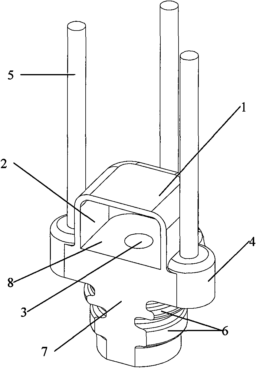
Figure 1 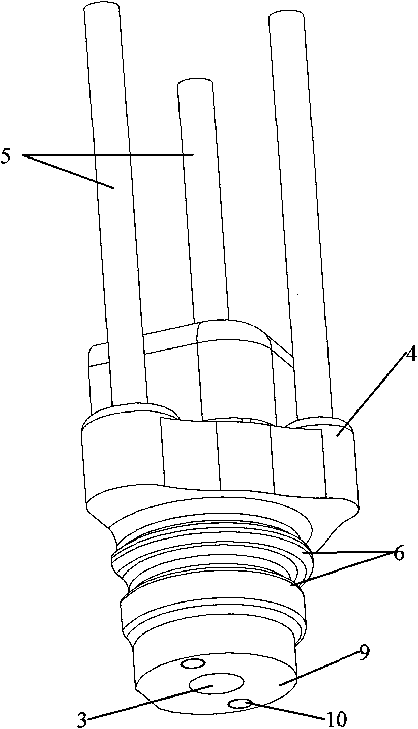
Figure 2 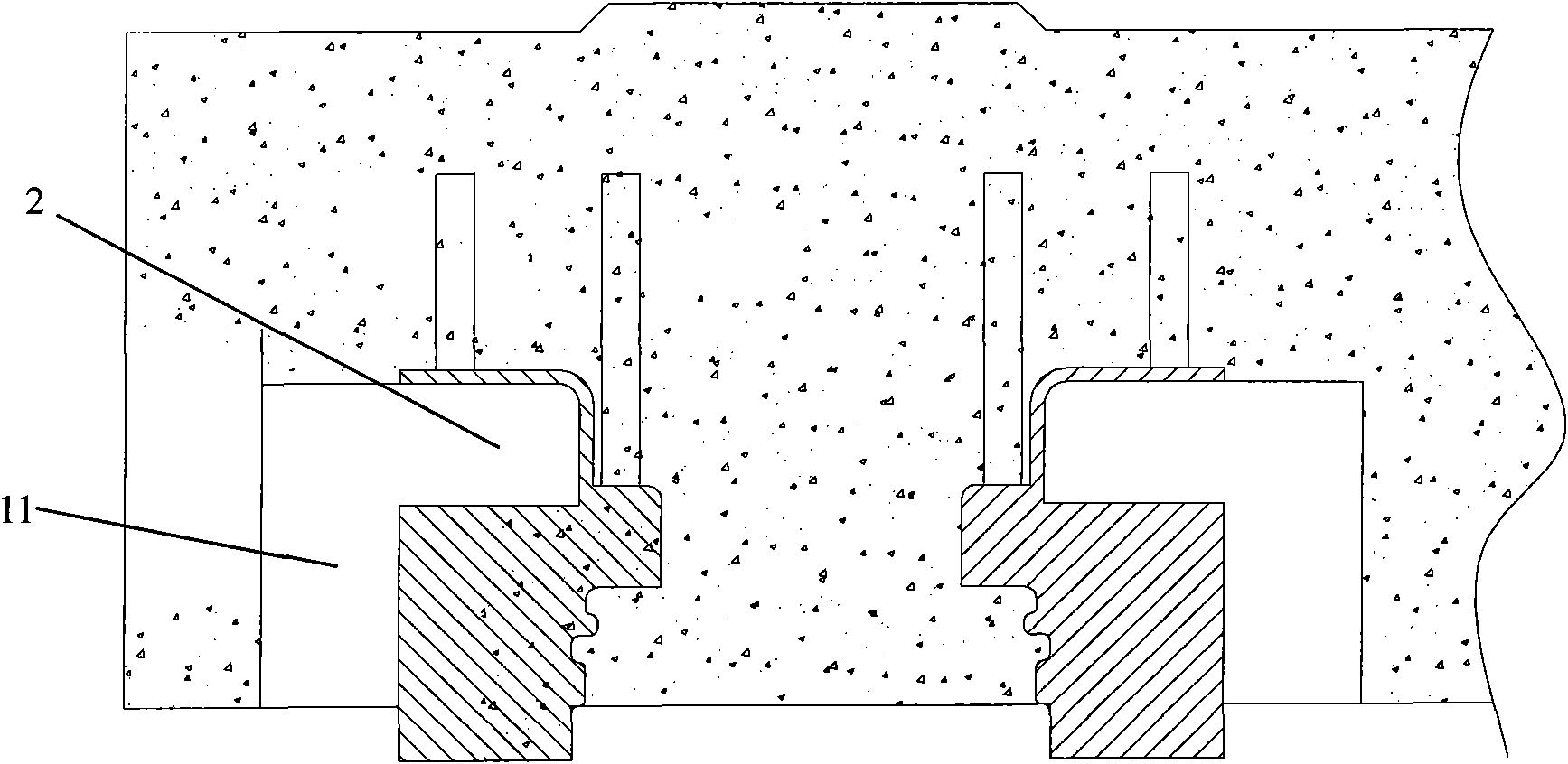
Figure 3
Abstract
Description
technical field
[0001] The invention relates to a structure of a concrete beam body, in particular to a structure of a concrete beam body connected with a stator. Background technique
[0002] In the existing maglev track beam technology, the entire functional area is an all-steel structure, and then the steel structure functional area is connected with the concrete beam body. The disadvantage is that the amount of steel used is large, resulting in high construction costs for the maglev track. The main way to overcome this shortcoming is to use concrete structure in the functional area, but the problem brought about by this is to solve the connection between the functional area of the concrete structure and the stator on the track beam. Contents of the invention
[0003] The purpose of the present invention is to provide a new type of embedded part for connecting the stator and the concrete beam, which can solve the problem of stable connection between the stator and th...
Examples
Embodiment Construction
[0013] The specific embodiments of the present invention will be described below in conjunction with the accompanying drawings.
[0014] Such as figure 1 and figure 2 As shown, the new embedded part provided by the present invention for connecting the stator and the concrete beam body of the maglev track beam is processed by cast iron, which includes the embedded part body 1; one end of the embedded part body 1 has a The installation cavity 2 is square; it is opened on the other end of the embedded part body 1 and opened through the bolt hole 3 passing through the embedded part body 1 to the installation cavity 2 and the bolt hole 3 arranged on the outside of the embedded part body 1 fixed structure.
[0015] Among them, the bottom surface of the installation cavity 2 (that is, the surface opened by the bolt hole 3) is the first installation contact surface 8, and the end surface of the embedded part body 1 with the bolt hole 3 is the second installation contact surface 9. ...