
Casting mould for high-pressure switch transitional coupling bus bar canister
A transitional connection and casting mold technology, which is applied in the direction of manufacturing tools, casting molding equipment, casting molds, etc., can solve the problems of huge production costs and the inability to realize the relative curve movement of the movable mold and the fixed mold in the casting mold, so as to save production costs Effect
Patent Information
- Authority / Receiving Office
- CN · China
- Patent Type
- Patents(China)
- Current Assignee / Owner
- Publication Date
- 2012-06-27
Smart Images
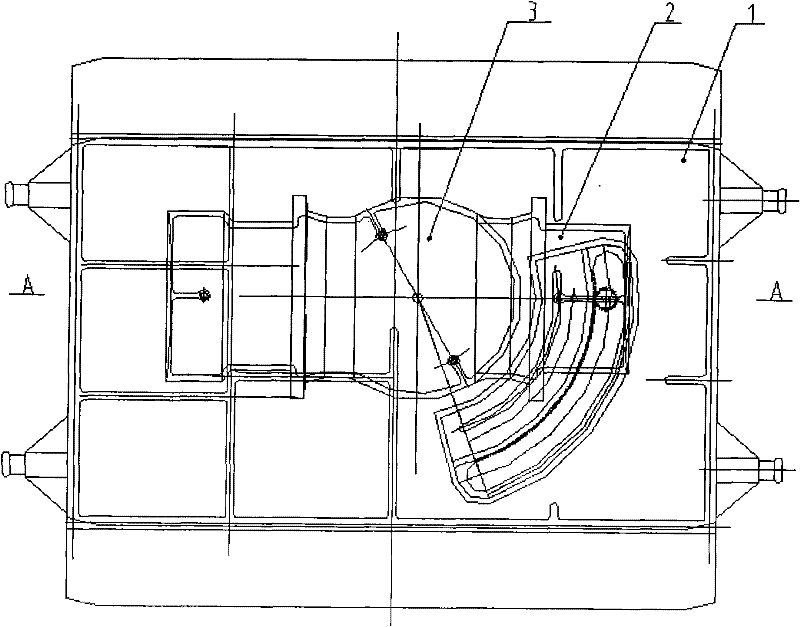
Figure 1 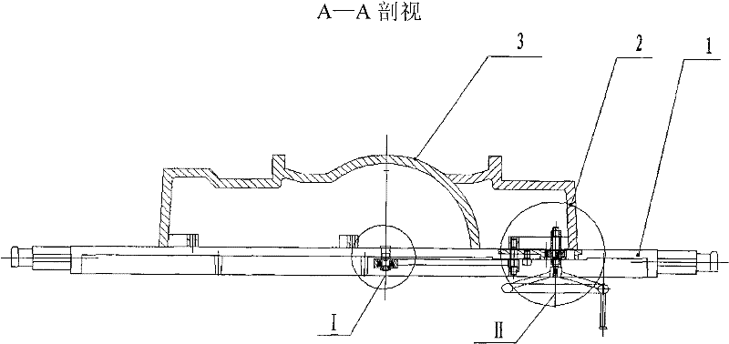
Figure 2 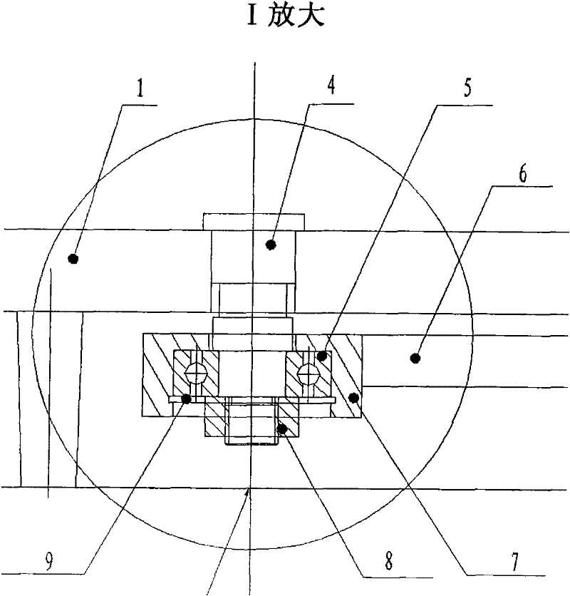
Figure 3
Abstract
Description
Technical field:
[0001] The invention relates to a mold for an elbow connection cylinder, in particular to a casting mold for a transition connection busbar cylinder of a high-voltage switch. Background technique
[0002] At present, when the bus barrel in the 252kV gas-insulated metal-enclosed switchgear (GIS) is arranged at the user's site, when it is necessary to turn, the branch bus joint shell transition in the form of a right angle is often used. On the one hand, this connection method cannot be effectively realized. The connection of the shortest distance also puts forward higher requirements on the area of the user's installation site. The use of acute angle transition connection is an effective way to solve this problem.
[0003] Because different areas of the same user site may have different requirements for the angle, and different sites of different users may also have different requirements for the angle. Using traditional casting molds, due to the differenc...
Examples
Embodiment Construction
[0022] Such as figure 1 As shown, the high-voltage switch transition connection busbar barrel casting mold includes two upper and lower templates with symmetrical structures. Form the shape of a sphere sandwiched between two cylinders. The cylinder part is provided with a flange structure. The hemisphere of each template and the half cylinder on one side are fixed, which is a fixed pattern 3, and the half cylinder on the other side It is movable, and it is a moving pattern 2. The moving pattern takes the center of the sphere of the fixed pattern as the center, takes the parting surface as the rotation plane, and rotates horizontally in the rotation plane. The moving pattern 2 rotates around the fixed pattern 3 through a gear mechanism.
[0023] combine figure 2 , image 3 , Figure 4 As shown, the gear mechanism includes setting a central shaft 4 on the bottom plate 1 where the center of the sphere of the fixed pattern 3 is located, the central shaft 4 is installed on the ...