
Mobile car positioning device and positioning method thereof
A mobile trolley and positioning device technology, applied in the direction of using electric/magnetic devices to transmit sensing components, etc., can solve the problems of unfavorable equipment maintenance and replacement, difficult installation and maintenance, and less application of mobile trolleys, so as to achieve free positioning and maintenance Easy, simple composition effect
Patent Information
- Authority / Receiving Office
- CN · China
- Patent Type
- Applications(China)
- Current Assignee / Owner
- Publication Date
- 2012-05-23
Smart Images
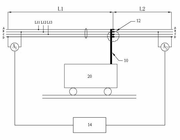
Figure 1 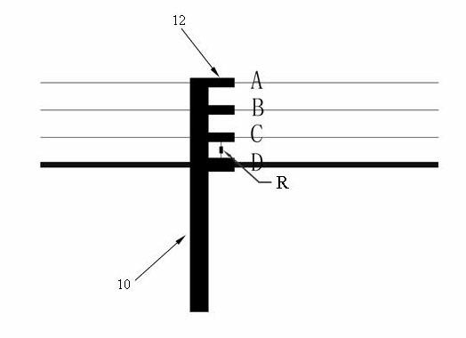
Figure 2 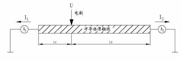
Figure 3
Abstract
Description
technical field
[0001] The invention relates to detection and positioning technology, in particular to a mobile trolley positioning device and positioning method. Background technique
[0002] Mobile trolleys are often used in production equipment in metallurgy, mining, chemical, textile and other industries. The position detection and positioning of mobile trolleys is a very important task. Currently commonly used mobile car positioning methods include the following:
[0003] 1) Use limit switches. A limit switch is installed on the traveling track of the trolley, and when the trolley reaches the limit switch, the action of the limit switch is triggered to send an in-position signal. The limit switches used can be mechanical, photoelectric or inductive, etc. Patent No. 200520040588.X, the patent entitled "Cutter Cart Origin Positioning and Locking Device" discloses this technology. The main advantage of using this positioning technology is that the structure is simple an...
Examples
Embodiment Construction
[0048] refer to figure 1 As shown, the present invention discloses a mobile trolley positioning device, comprising:
[0049] Power trolley, connected to a three-phase power supply. exist figure 1 In the shown embodiment, the power trolley line includes three phases A, B, and C, and is made of common conductive materials. The three-phase trolley lines A, B, and C are respectively connected to three-phase power sources L11, L12, and L13.
[0050] The semiconductor trolley line D is arranged in parallel with the three phases A, B, and C of the power trolley line and conducts with the power trolley line. The semiconductor trolley line has a uniform resistance distribution.
[0051] The collector 10, the first end of the collector 10 is connected to the power trolley line A, B, C and the semiconductor trolley D, the second end of the collector is connected to the mobile trolley 20 to supply power to the mobile trolley 20, the power collector 10 The first end has a brush 12 which...