
Hydraulic suspension type blood pump
A suspension type, blood pump technology, applied in the field of medical devices, can solve problems such as increasing the complexity of the control system, and achieve the effects of reducing heat generation and complex structure, facilitating suspension, and facilitating lightweighting
Patent Information
- Authority / Receiving Office
- CN · China
- Patent Type
- Patents(China)
- Current Assignee / Owner
- Publication Date
- 2015-02-25
- Estimated Expiration
- Not applicable · inactive patent
Smart Images
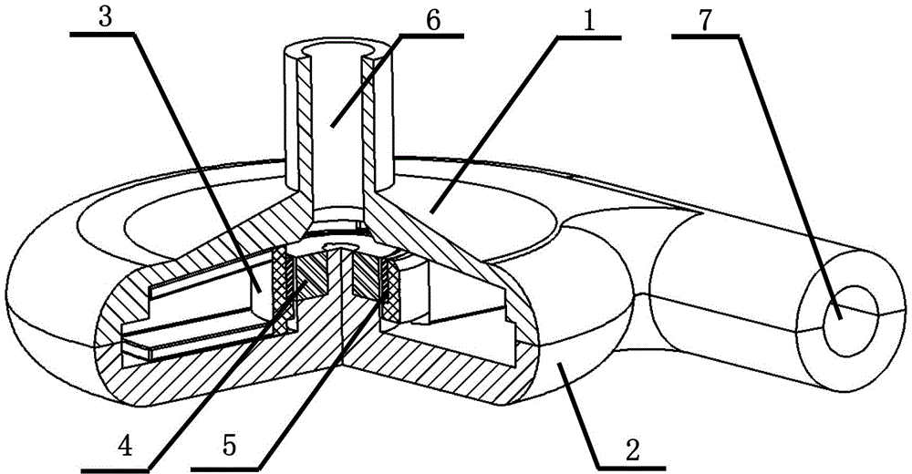
Figure 1 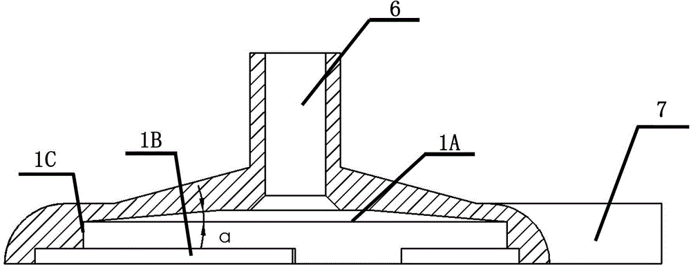
Figure 2 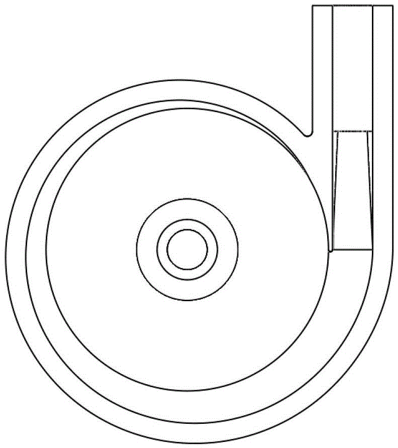
Figure 3
Abstract
Description
technical field
[0001] The invention relates to a medical device, in particular to a hydraulic suspension blood pump. Background technique
[0002] At present, the bearings used in blood pumps mainly include mechanical contact bearings and non-contact bearings. Mechanical contact bearings have the problem of motor bearing wear and frictional heating that induce thrombus, which seriously restricts the development of blood pumps and their wide application in clinical practice. Therefore, non-contact bearings have become a research hotspot in modern blood pumps.
[0003] Non-contact bearings are divided into active control suspension bearings, passive control suspension bearings, and hybrid bearings. Active control levitation bearings are mainly electromagnetic levitation bearings. For example, see US Patent No. 7,470,246, which has been successfully applied to blood pumps. It mainly suspends the rotor in the pump by energizing the electromagnetic coil to generate magnetic fo...
Examples
Embodiment Construction
[0029] The purpose and effect of the present invention will become more obvious by referring to the accompanying drawings to describe the present invention in detail.
[0030] As shown in the figure, the hydraulic suspension blood pump of the present invention includes a pump upper cover 1, a pump lower cover 2, an impeller rotor 3, a stator electromagnetic coil 4 and a drive magnet 5; wherein: the impeller rotor 3, the stator electromagnetic coil 4 and the drive magnet The magnets 5 are placed in the cavity formed by the pump cover 1 and the pump lower cover 2, the drive magnets 5 are fixed on the inner wall of the impeller rotor 3, and the impeller rotor 3 and the stator electromagnetic coil 4 are coaxially installed.
[0031] Such as figure 2 and image 3 As shown, there is a pump inlet 6 at the top of the pump loam cake 1, and the upper half of the pump outlet is opened at the bottom. There are two parts of the cavity 1B, the upper part of the cavity 1A on the upper cov...