
Energy-saving oil pump
A technology for energy-saving machines and oil pumps, applied to pump components, mechanical equipment, machines/engines, etc., can solve problems that cannot be overcome at the same time, large defects, etc., and achieve the effect of simple structure, low production cost, and not easy to leak
Patent Information
- Authority / Receiving Office
- CN · China
- Patent Type
- Applications(China)
- Current Assignee / Owner
- Publication Date
- 2013-04-17
- Estimated Expiration
- Not applicable · inactive patent
Smart Images
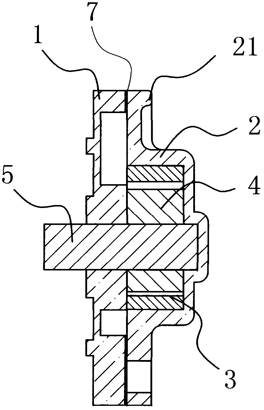
Figure 1 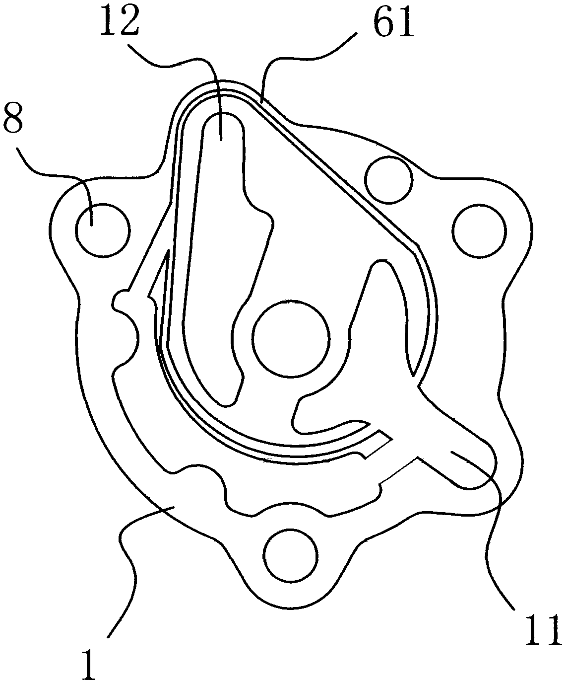
Figure 2 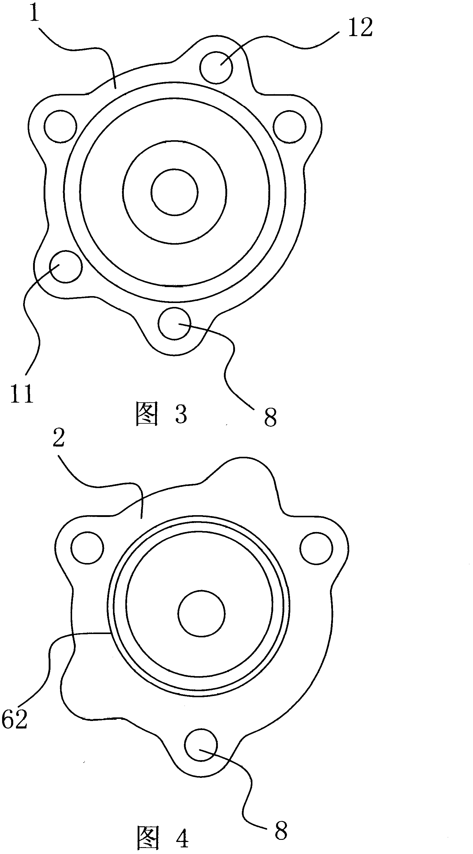
Figure 3
Abstract
Description
technical field
[0001] The invention belongs to the technical field of power devices, and in particular relates to an energy-saving oil pump. Background technique
[0002] Oil pumps are composed of pump body, stator, rotor and other parts, and are widely used in various industries. The existing oil pump has high manufacturing cost, great assembly difficulty, unsatisfactory sealing performance and low mechanical strength. For this reason, people have carried out long-term exploration, put forward various solutions.
[0003] For example, Chinese patent literature discloses an improved diesel engine oil pump [Patent No.: 200420091807.2], its basic structure includes: a pump casing, a rotor slidingly fitted with the inner cavity of the pump casing, and an eccentric arrangement on the inner cavity of the rotor to engage with the inner cavity of the rotor The rotating core and the mandrel matched with the central hole of the rotating core are characterized in that: the mandrel i...
Examples
Embodiment Construction
[0019] like figure 1 As shown, the energy-saving oil pump includes a pump body 1 and a pump cover 2 that are interlocked with each other. A cylindrical stator 3 is fixed on the inner wall of the pump cover 2, and a rotor 4 is arranged inside the stator 3. The rotor 4 is sleeved on the rotor On the shaft 5 , one end of the rotor shaft 5 is rotationally connected with the pump cover 2 , and the other end passes through the pump body 1 and extends out of the pump body 1 . The pump body 1 is provided with an oil inlet hole 11 and an oil outlet hole 12 , and an oil passage around the periphery of the rotor 4 is provided between the joint surface of the pump body 1 and the pump cover 2 . The shape of the state-owned channel here is similar to the peripheral shape of the pulley drive structure.
[0020] like Figure 5 As shown, the outer end of the pump cover 2 is provided with reinforcing ribs 21 arranged along the edge, and the reinforcing ribs 21 are connected with the pump cove...