
Ignition and stable combustion device for industrial gas burner
A technology of stabilizing combustion device and industrial gas, which is applied in combustion ignition, gas fuel burners, burners, etc., can solve the problem of insufficient ignition flame stability, and achieve the effect of reducing NOx
Patent Information
- Authority / Receiving Office
- CN · China
- Patent Type
- Patents(China)
- Current Assignee / Owner
- Publication Date
- 2015-09-09
Smart Images
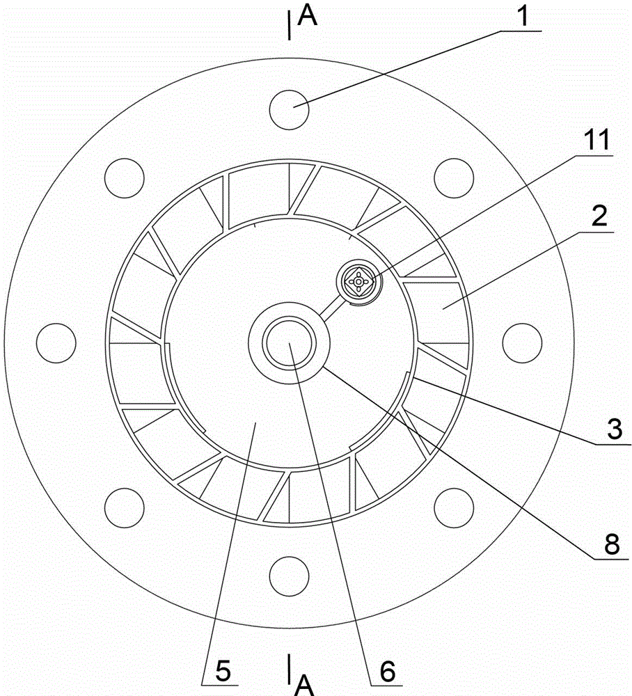
Figure 1 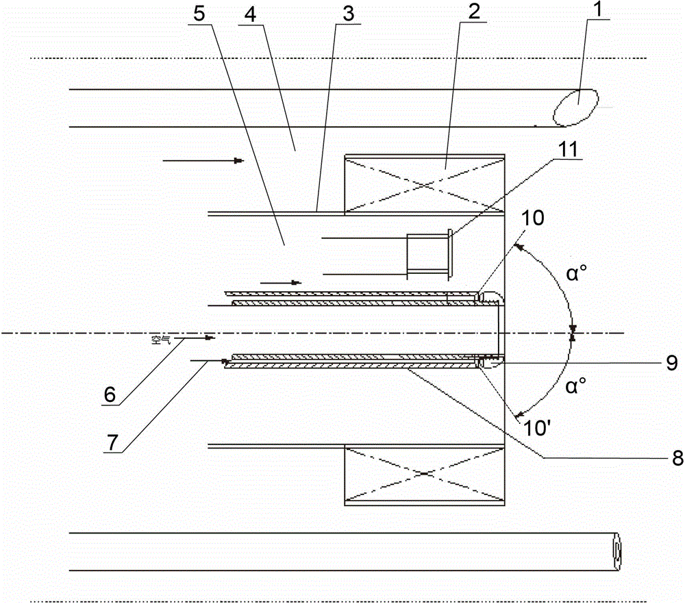
Figure 2 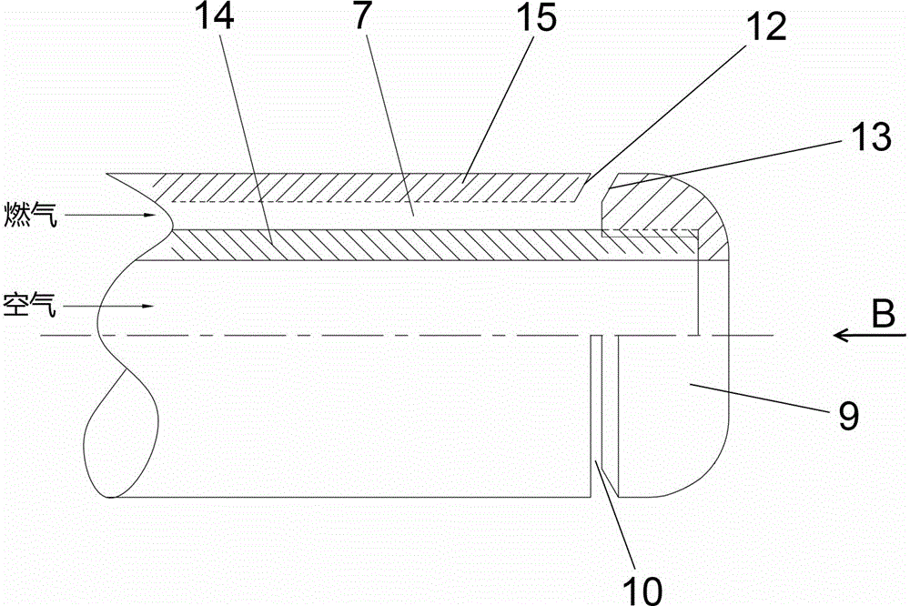
Figure 3
Abstract
Description
technical field
[0001] The invention relates to an ignition device for an industrial gas burner and a central stable combustion method thereof. The ignition device has high ignition success rate, stable flame and low NOx emission, and belongs to the technical field of industrial gas burners. Background technique
[0002] At present, with the large-scale use of domestic gas, the improvement of the West-East Gas Transmission Line, and the coal-to-gas heating projects in Beijing, Xinjiang, Tianjin and other places are being carried out in depth. In addition, all kinds of oilfield gas and industrial waste gas are also collected and used as industrial gas, which puts forward higher requirements on the performance of the burner. Gas burners are developing in the direction of high power, energy saving and stability.
[0003] Known high-power gas burners or low calorific value gas burners use the supply mode of low-speed combustion-supporting air in the center, and the ignition gun...
Examples
Embodiment Construction
[0014] figure 1 and figure 2 It is a schematic diagram of the structure of the present invention. As can be seen from the figure, an industrial gas burner ignition and stable combustion device of the present invention includes a central tube 8, a central tube 3, a swirler 2, an ignition gun 11 and a main gas gun 1, and is characterized in that: the central tube 8 includes Central tube inner tube 14 and central tube outer tube 15, said central tube inner tube 14 is placed in said central tube outer tube 15, and coaxially arranged, said central tube inner tube 14 and said central tube outer tube 15 are The gas inlet channel 7 of the central annular gas injection device, the upper end of the gas inlet channel 7 of the central annular gas injection device is blocked by an annular gas channel cover 9, and the inner periphery of the annular gas channel cover 9 is in contact with the The central tube inner tube 14 upper end is fixedly connected, by image 3 and Figure 4 It can ...