
Vertical cooling and waste heat recovery furnace for sinters
A technology of waste heat recovery and sintering, which is applied in furnaces, waste heat treatment, furnace components, etc., can solve the problems of high rate of rapid cooling and crushing of sintered ore, high air leakage rate of sintered ore, high cost of heat recovery, etc., and achieve airflow direction Optimization, saving fan power consumption, and high production reliability
Patent Information
- Authority / Receiving Office
- CN · China
- Current Assignee / Owner
- Publication Date
- 2014-04-02
Smart Images
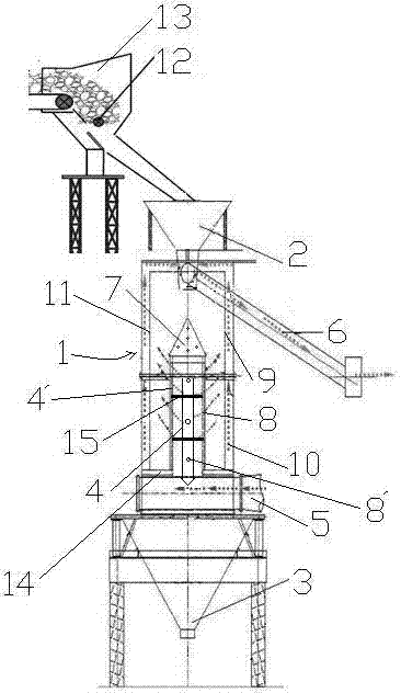
Figure 1
Abstract
Description
Technical field
[0001] The invention relates to the fields of sinter cooling and waste heat recovery, and in particular to a vertical cooling and waste heat recovery furnace for sinter. Background technique
[0002] According to statistics, the sensible heat of sinter cooling exhaust gas accounts for about 19% to 35% of the total energy consumption of the sintering process. There are three main ways to recover and utilize the waste heat of sinter cooling exhaust gas in China: First, the waste flue gas is directly purified and used as a sintering machine ignition furnace. Combustion air or used to preheat the mixture to reduce fuel consumption. This method is relatively simple, but the waste heat utilization is limited, generally not exceeding 10% of the flue gas volume; second, the waste flue gas is generated through a heat pipe device or a waste heat boiler to generate steam, which is incorporated into the steam pipe network to replace some coal-fired boilers; third The st...
Examples
Embodiment Construction
[0042] like figure 1 As shown, the present invention includes a feed hopper 2 and a discharge hopper 3 communicated with the top and bottom of the cooling chamber 1 respectively (both the discharge hopper and the feed hopper are funnel-shaped). The cooling chamber 1 is provided with first and second air pipes 4 and 4' sequentially in the same circle center, and the walls of the first and second air pipes 4 and 4' are respectively provided with a plurality of air outlet holes 8 and 8 '. still as figure 1 As shown, the top of the first air duct 4 is provided with a conical distributor 7 , and the bottom of the second air duct 4 ′ communicates with the cold air inlet duct 5 . still as figure 1 As shown, the first air duct 4 is separated by a partition 15 into three cavities, upper, middle and lower, which are not communicated with each other. The second air duct 4' passes through the lower and middle cavities and then extends into the upper cavity. The air output of the air o...