
Lighting lamp with adjustable size
A technology for lighting lamps and lighting units, which is applied to lighting devices, lighting auxiliary devices, lighting and heating equipment, etc., and can solve problems such as inability to freely transform shapes, changes in the intensity of light, and inability to change the size of lamps, etc., and achieve a simple structure. Effect
Patent Information
- Authority / Receiving Office
- CN · China
- Patent Type
- Applications(China)
- Current Assignee / Owner
- Publication Date
- 2014-05-21
- Estimated Expiration
- Not applicable · inactive patent
Smart Images
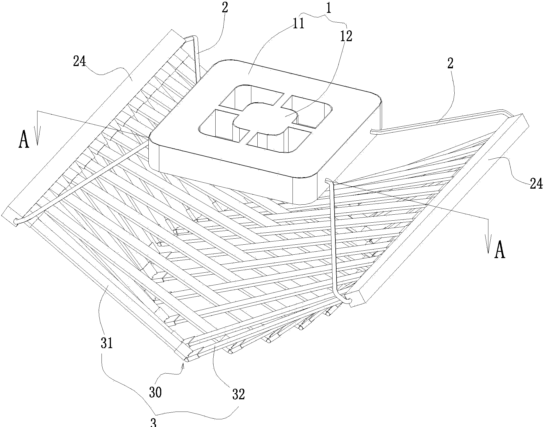
Figure 1 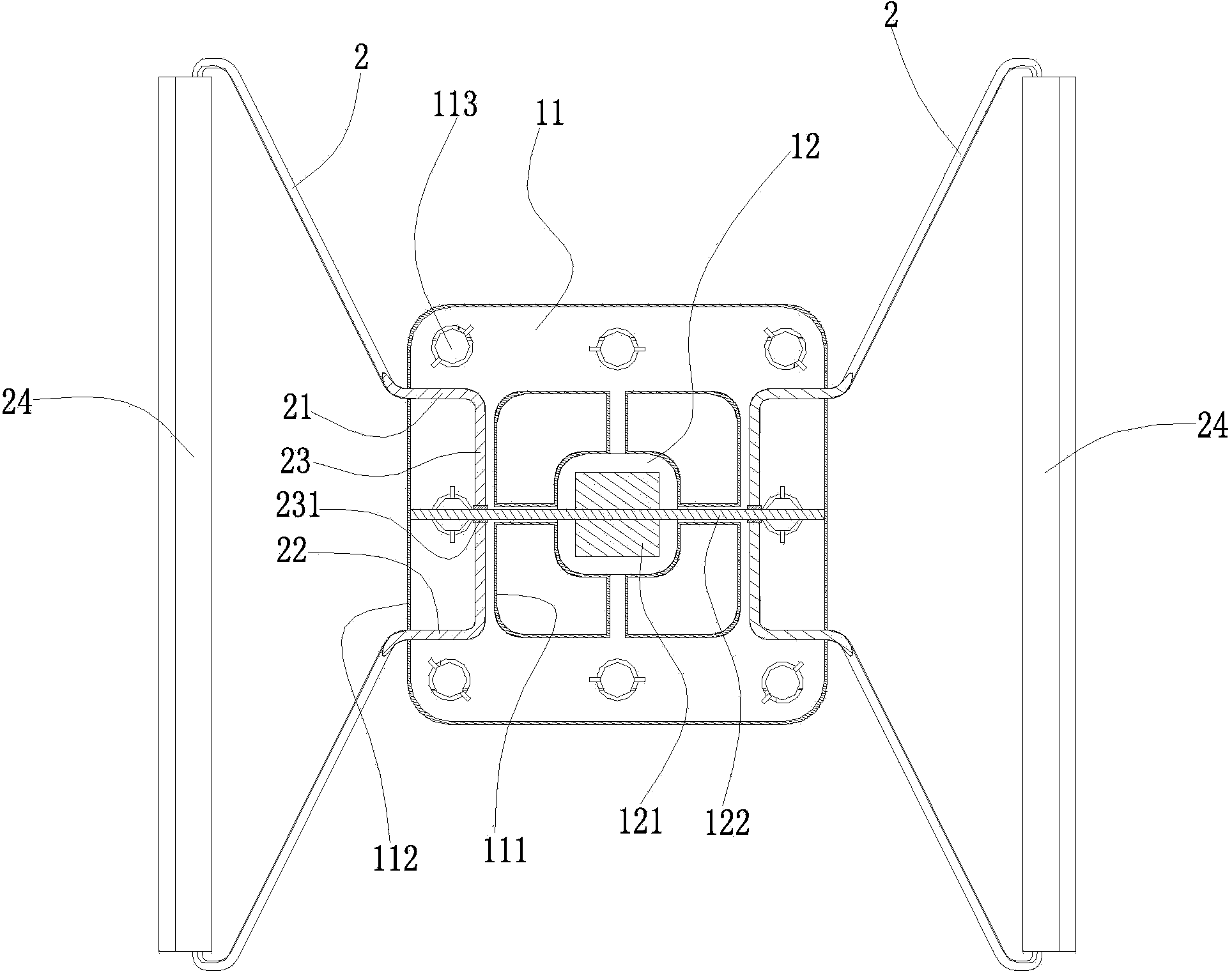
Figure 2 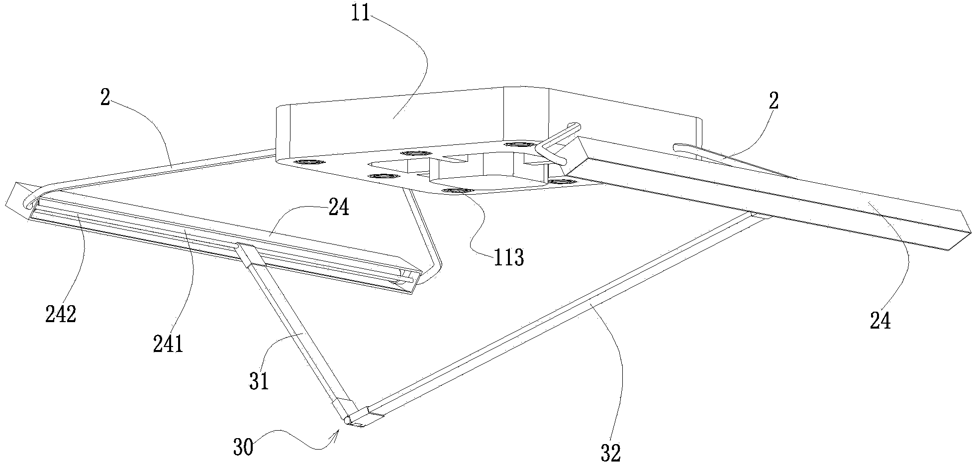
Figure 3
Abstract
Description
Technical field:
[0001] The invention relates to a size-adjustable lighting fixture. Background technique:
[0002] The existing lighting fixtures have the following defects after they are fixedly installed: 1. The size of the lighting fixtures usually cannot be changed. 2. The decorative parts installed on the lamps are also fixed and cannot be freely changed in shape. 3. The light emitted by the lamp cannot change in intensity with the change of the shape, so as to adapt to different scenarios. Invention content:
[0003] The object of the present invention is to provide a size-adjustable lighting fixture, which has a simple structure and the size of the whole lamp can be changed freely.
[0004] A lighting fixture with adjustable size, including a ceiling cup, a bracket, and a first lighting unit installed on the bracket, characterized in that: a bracket driving device is arranged inside the ceiling cup, and the bracket extends into the ceiling The back of the disk i...
Examples
Embodiment Construction
[0019] As shown in the figure, a lighting fixture with adjustable size includes a ceiling plate 1, brackets 2 extending into the left and right sides of the ceiling plate, a first lighting unit 241 installed on each bracket, and several Then arrange the decoration unit 3.
[0020] The ceiling plate 1 includes an annular outer disc body 11, and an inner disc body 12 connected to the inner side wall of the outer disc body through front, rear, left and right connecting arms and arranged at the center of the outer disc body. There is a groove, and a bracket driving device 121 is installed in the inner disk body 12. The driving device is a motor, and its output shaft is a screw rod 122. The two ends of the screw rod 122 pass through the grooves on the left and right connecting arms and then extend into the outer disk. In body 11. The outer disc body 11 is respectively provided with a circular hole-shaped front guide portion and a rear guide portion on the left and right sides of i...