
Milling and clamping device for eccentric upper head flange
A technology of head flange and clamping device, which is applied in the field of machining, can solve the problems of long clamping time, multiple milling machine changes, low efficiency, etc., achieve high uniformity, reduce alignment difficulty, and improve pass rate Effect
Patent Information
- Authority / Receiving Office
- CN · China
- Patent Type
- Patents(China)
- Current Assignee / Owner
- Publication Date
- 2016-05-25
- Estimated Expiration
- Not applicable · inactive patent
Smart Images
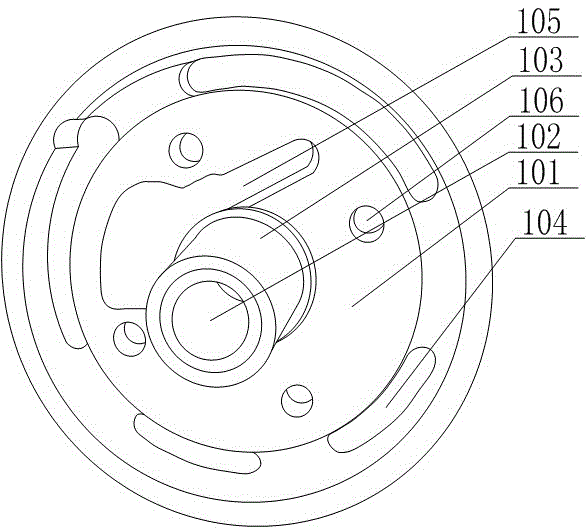
Figure 1 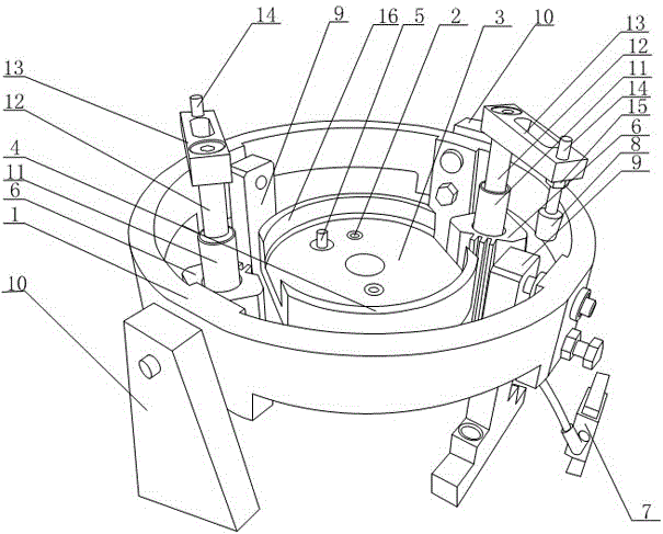
Figure 2
Abstract
Description
technical field
[0001] The invention relates to a machined one, in particular to a milling and clamping device for an eccentric upper head flange. Background technique
[0002] The eccentric upper head flange is a special flange in the pipeline circulation industry, as attached figure 1 As shown, it includes a circular sealing plate 101, an axis hole 102 is opened on the axis of the circular sealing plate 101, and an axis sleeve 103 is installed on the axis hole 102, and a Four through-holes 106 distributed symmetrically around the axis are used to pass through and fix the measurement signal terminals, and arc-shaped strip holes 104 are arranged around the sealing plate 101 for the installation of seals An irregular groove 105 is recessed and formed on the sealing plate 101 for installing the signal measuring block, and its shape matches it.
[0003] At present, the processing technology of the eccentric upper head flange is as follows: firstly, the center hole is drilled ...
Examples
Embodiment
[0022] Such as figure 2 As shown, a milling and clamping device for an eccentric upper head flange according to the present invention includes a positioning ring 1, the positioning ring 1 is in the shape of a ring, and a pair of inner columns 9 are installed on the inner side of the positioning ring 1, and the outer side of the positioning ring 1 An outer column 10 is installed, and the inner column 9 and the outer column 10 are evenly arranged on the positioning ring 1, and the connecting line of the inner column 9 and the connecting line of the outer column 10 are basically vertically distributed, and the positioning ring 1 passes through the inner column 9 and the outer column. 10 is installed on a milling machine, and a cylinder 6 corresponding to the outer column 10 is installed on the inner side of the positioning ring 1. The cylinder 6 is a double-channel cylinder, and the outer channel drives the rotating shaft 11 to rotate, and the inner channel drives the push rod 12...