
LED driving circuit applicable to silicon controlled rectifier light modulator, and control circuit thereof
A technology of LED drive and control circuit, applied in the direction of electric lamp circuit layout, light source, electric light source, etc., can solve the problem of high cost
Patent Information
- Authority / Receiving Office
- CN · China
- Current Assignee / Owner
- Publication Date
- 2015-12-09
Smart Images
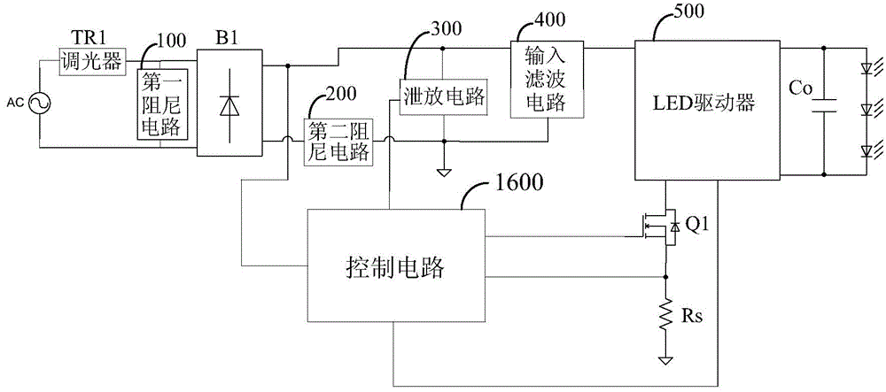
Figure 1 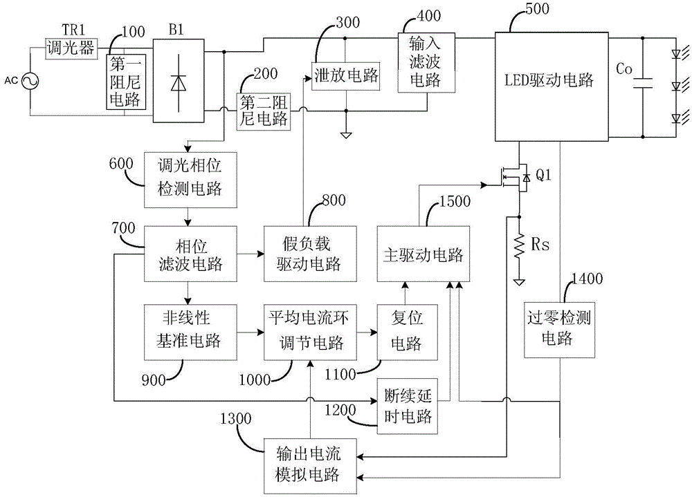
Figure 2 
Figure 3
Abstract
Description
technical field
[0001] The invention relates to LED driving technology, in particular to an LED driving circuit and a control circuit suitable for a thyristor dimmer. Background technique
[0002] Compared with conventional light sources such as incandescent lamps and fluorescent lamps, LED lamps have the advantages of high efficiency, good directionality, good stability, high reliability, and long life, so they are widely used in various places. The thyristor dimming method is one of the most widely used dimming methods for LEDs at present, and it is widely used in fields such as stage lighting and ambient lighting. As we all know, due to the characteristics of the thyristor dimmer, it needs a certain maintenance current to ensure the conduction, so it cannot be directly connected in series with the live line of the LED driver, and the LED driver circuit needs to be modified accordingly.
[0003] The usual solution in the prior art is to carry out two-stage dimming: that i...
Examples
Embodiment Construction
[0143] The present invention will be further described below in conjunction with specific embodiments and accompanying drawings, but the protection scope of the present invention should not be limited thereby.
[0144] refer to figure 1 , the LED drive circuit applicable to the thyristor dimmer in this embodiment includes: thyristor dimmer TR1, rectifier bridge B1, first damping circuit 100, second damping circuit 200, bleeder circuit 300, input filter The circuit 400, the LED driver 500, the control circuit 1600, the switch tube Q1, the sampling resistor Rs and the output capacitor Co.
[0145] refer to figure 2 , the control circuit 1600 may include: dimming phase detection circuit 600, phase filter circuit 700, dummy load drive circuit 800, nonlinear reference circuit 900, average current loop adjustment circuit 1000, reset circuit 1100, intermittent delay circuit 1200, output A current simulation circuit 1300 , a zero-crossing detection circuit 1400 and a main driving c...