
All-digital phase-locked loop in frequency conversion domain and phase-locked control method
An all-digital phase-locked loop and phase-locked loop technology, applied in the field of electronic information, can solve the problems of poor versatility and poor self-adaptation of the phase-locked loop, and achieve the goal of reducing frequency, reducing phase jitter, and enhancing stability Effect
Patent Information
- Authority / Receiving Office
- CN · China
- Patent Type
- Patents(China)
- Current Assignee / Owner
- Publication Date
- 2018-11-06
- Estimated Expiration
- Not applicable · inactive patent
Smart Images
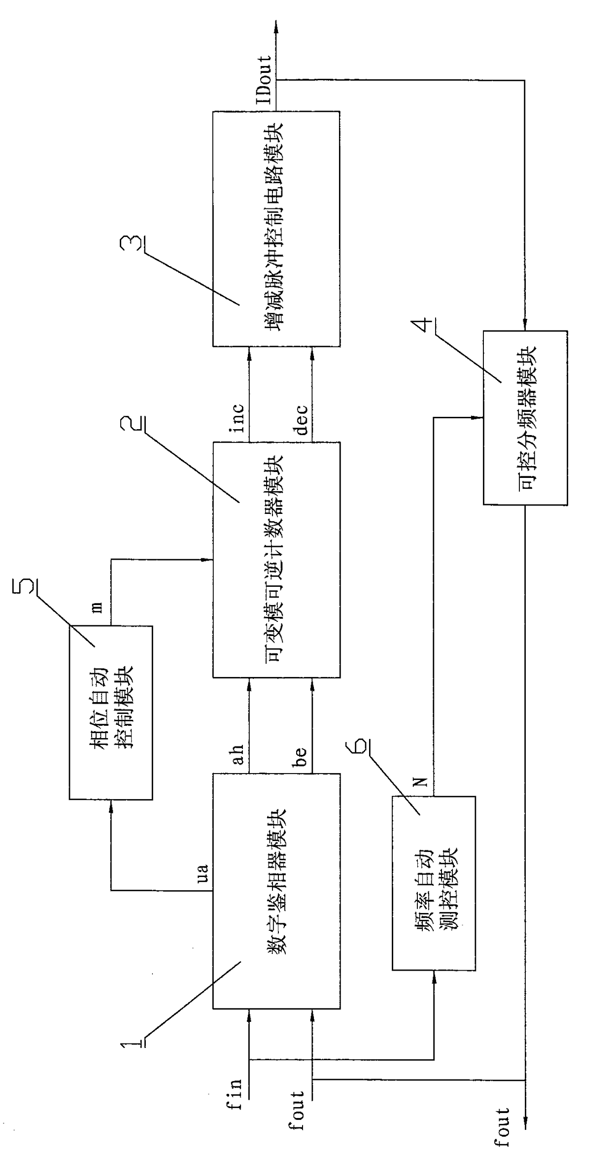
Figure 1 
Figure 2 
Figure 3
Abstract
Description
technical field
[0001] The invention belongs to the technical field of electronic information, and in particular relates to an all-digital phase-locked loop in the frequency conversion domain and a phase-locked control method applied to a system on chip (SOC). Background technique
[0002] The all-digital phase-locked loop is widely used in the fields of communication, signal processing, modulation and demodulation, clock synchronization, frequency synthesis and automatic control, and has become an indispensable basic component in various electronic equipment.
[0003] The existing all-digital phase-locked loop has the following defects:
[0004] One is that the phase-locking range is narrow, the purpose is single, and the versatility is not strong. The existing all-digital phase-locked loop is designed by the designer based on a single fixed frequency domain in a certain application field. The frequency locking range of each phase-locked loop is relatively small. When the ...
Examples
Embodiment Construction
[0052] All-digital phase-locked loop in frequency conversion domain, including digital phase detection module 1, variable mode reversible counter module 2, increase and decrease pulse control circuit module 3, controllable frequency divider module 4, phase automatic measurement and control module 5 and frequency automatic measurement and control module 6 , using electronic design automation technology to complete the design of each module circuit.
[0053] The digital phase detector module 1 has two signal input terminals and three signal output terminals. The two signal input terminals are respectively the fin signal input terminal and the fout signal input terminal. Ring the rising edge of the input signal fin and the output signal fout, judge its phase error and polarity, and generate the leading phase difference polarity signal ah, the lagging phase difference polarity signal be, and the phase difference and frequency difference signal ua reflecting the input and output sig...