

A connection structure and a connection system between a column and a closed beam
A technology for connecting structures and beams, which is applied to building components, building structures, walls, etc., can solve the problems of weakening mechanical properties such as beam resistance to torsion, etc., and achieve simple and easy structure, safe structure stress, and convenient processing and loading and unloading Effect
Patent Information
- Authority / Receiving Office
- CN · China
- Patent Type
- Patents(China)
- Current Assignee / Owner
- Publication Date
- 2018-07-13
Smart Images
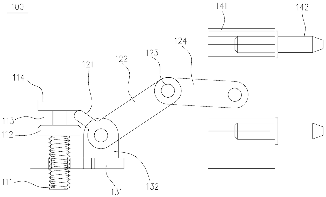
Figure 1 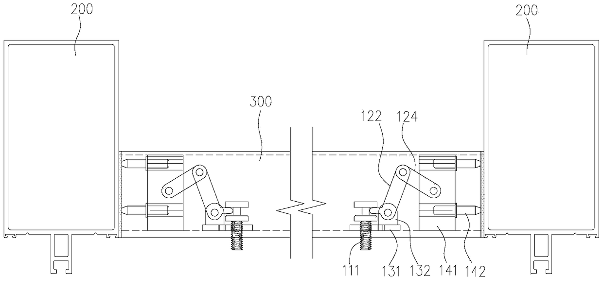
Figure 2 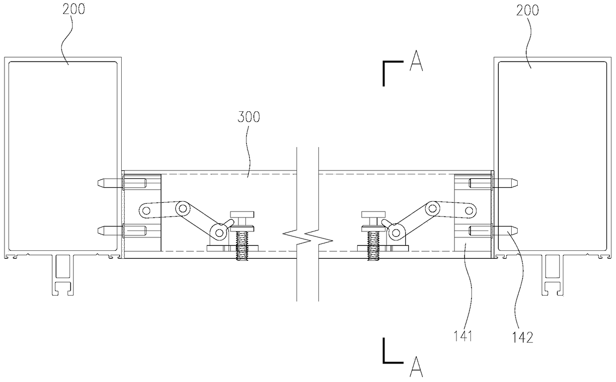
Figure 3
Abstract
Description
technical field
[0001] The invention relates to the technical field of building curtain walls, in particular to a connection structure for connecting a frame-type closed beam and a column, and a system for connecting a column and a closed beam using the connection structure. Background technique
[0002] The curtain wall is called the clothes of the building. The design selection and installation quality of the curtain wall not only directly affect the image of the entire building, but also affect the use function of the entire building, and also affect the operation and maintenance costs in the future. The main keel of the frame-type curtain wall is generally composed of aluminum alloy columns and aluminum alloy beams. When installing, first install the columns (or beams) on the main structure, and then install the beams (or columns). The frame is composed of columns and beams, and then Fix the panel material unit assembly on the sash, and carry out sealant joint treatment ...
Examples
Embodiment
[0017] refer to Figure 1-4 , the present embodiment provides a connection structure 100 for connecting a frame-type closed beam to a column, and a system for connecting a column to a closed beam using the connection structure 100 .
[0018] The connection structure 100 includes a control screw 111, a base 131, a linkage mechanism, a fastening ferrule 141 and a fastening pin 142, such as figure 1 shown. A connection block 132 for connecting with the linkage mechanism is provided on the base 131 , and a screw hole for the control screw 111 to pass through is provided beside the connection block 132 . A screw cap 114 is disposed on the control screw 111 , and a ring of protruding edge 112 is disposed under the screw cap 114 . The locking position 113 is formed by the screw cap 114 , the protruding edge 112 below the screw cap 114 , and the distance between them. The control screw 111 passes through the screw hole on the base 131 , and the control screw 111 can move up and dow...