
Harmonic management device for intermediate frequency furnace
A technology for harmonic control and intermediate frequency furnace, which is applied to harmonic reduction devices and AC networks to reduce harmonics/ripples, etc. wave effect
Patent Information
- Authority / Receiving Office
- CN · China
- Patent Type
- Applications(China)
- Current Assignee / Owner
- Publication Date
- 2017-02-08
- Estimated Expiration
- Not applicable · inactive patent
Smart Images
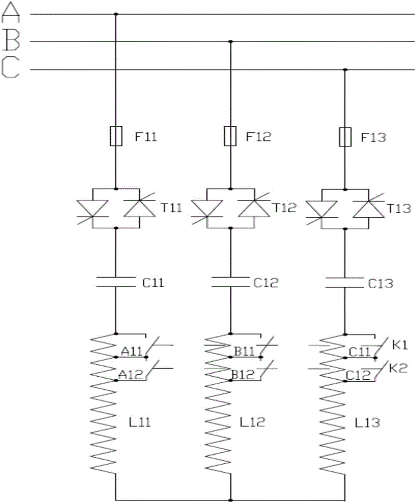
Figure 1 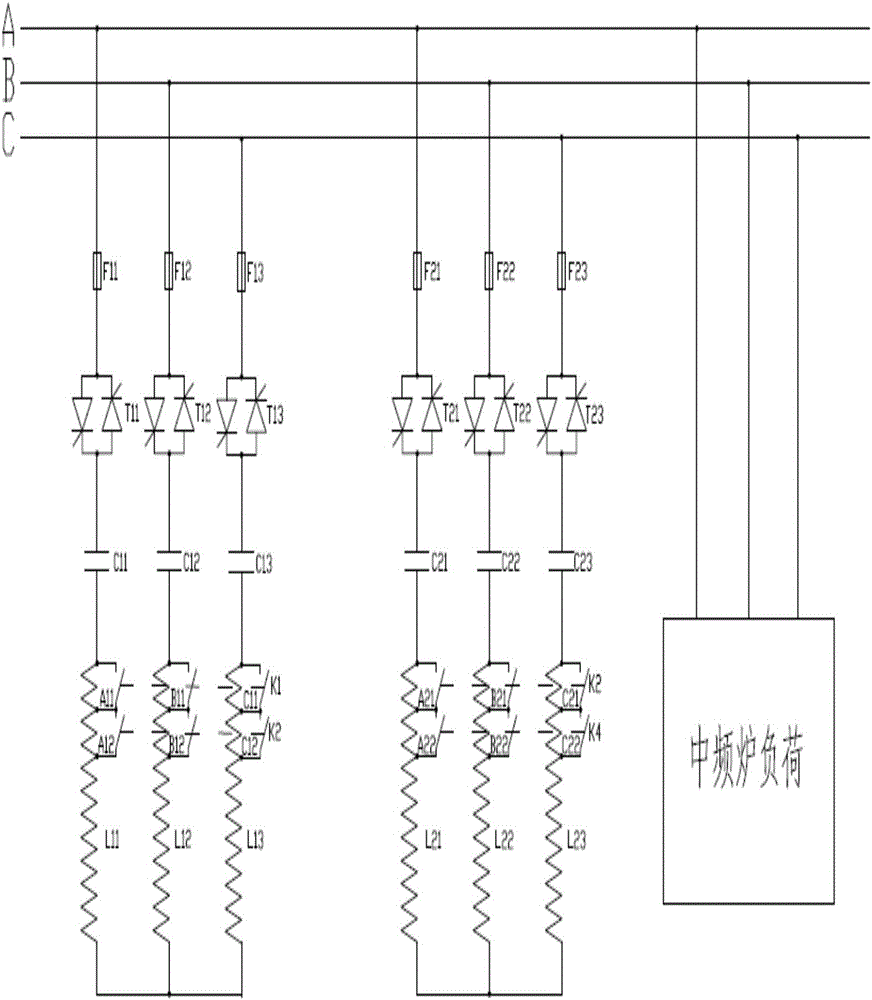
Figure 2
Abstract
Description
Technical field
[0001] The invention relates to a harmonic control device for an intermediate frequency furnace. Background technique
[0002] The basic working principle of the intermediate frequency furnace is to use thyristor components to transform the power frequency three-phase AC power supply into an intermediate frequency single-phase AC power supply, and supply the intermediate frequency furnace load composed of a capacitor and an induction coil. The induction coil generates an alternating electromagnetic field. The conductive material is placed In the induction coil, the eddy current is generated in the material due to electromagnetic induction, and the electric energy is converted into heat energy to heat the material by the action of resistance. The induction coil and compensation capacitor in the intermediate frequency furnace form an LC oscillation circuit. The LC circuit has a natural oscillation frequency of fo. When the output frequency f of the inverter of the i...
Examples
Embodiment Construction
[0017] The present invention will be further described below in conjunction with the accompanying drawings of the specification.
[0018] Such as figure 1 As shown, one of the LC filter circuit structure diagrams in a harmonic control device for an intermediate frequency furnace of the present invention includes three-phase power lines A-phase, B-phase and C-phase, and the three-phase power line A phase and fuse F11, Anti-parallel thyristor T11 and filter capacitor C11 are connected in series; Phase B of the three-phase power line is in series with fuse F12, anti-parallel thyristor T12, and filter capacitor C12; Phase C of the three-phase power line is connected with fuse F13, anti-parallel thyristor T13, and filter The capacitor C13 is connected in series; the output ends of the filter capacitors C11, C12, and C13 are electrically connected to the input ends of the filter windings of the three-phase filter reactor; the three-phase filter reactors are filter reactor L11 and filter...