
Intelligent low-voltage power capacitor
A low-voltage electric power and capacitor technology, which is applied in electrical components, emergency protection circuit devices, reactive power compensation, etc., can solve the problems of single capacitors without harmonic protection, capacitors burnt and damaged, and imperfect protection functions, etc., to achieve perfect protection functions , Reduce interference between internal signals, and compact structure
Patent Information
- Authority / Receiving Office
- CN · China
- Patent Type
- Applications(China)
- Current Assignee / Owner
- Publication Date
- 2017-02-22
- Estimated Expiration
- Not applicable · inactive patent
Smart Images
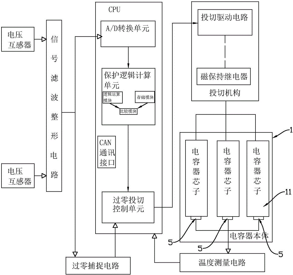
Figure 1 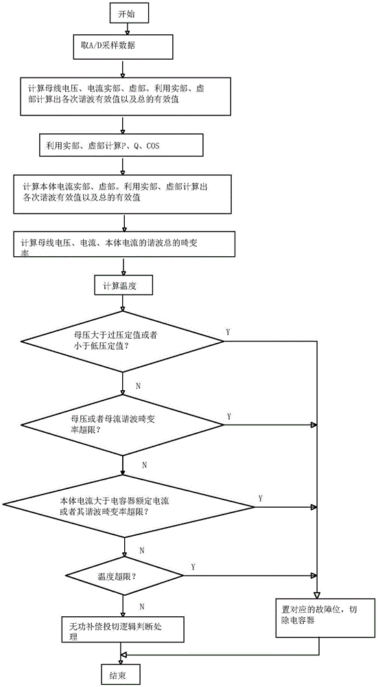
Figure 2 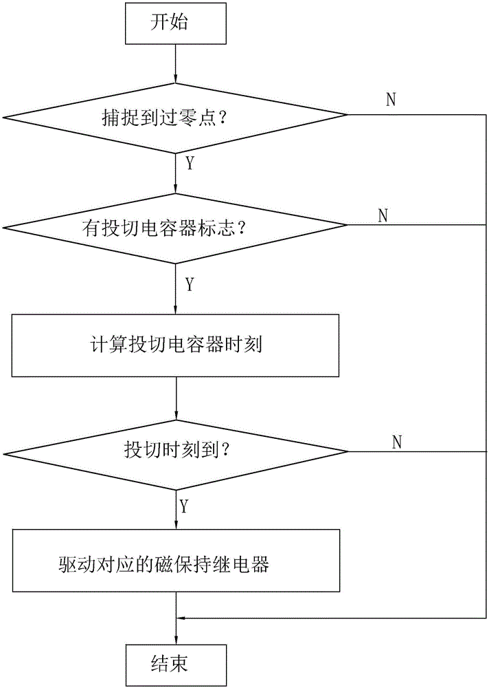
Figure 3
Abstract
Description
technical field
[0001] The invention relates to the technical field of power equipment, specifically a power capacitor. Background technique
[0002] Smart capacitor is an intelligent reactive power compensation device integrating modern measurement and control, power electronics, network communication, automation control, power capacitor and other advanced technologies. It has better compensation effect, smaller size, lower power consumption and cheaper price. It is characterized by more flexible use, more convenient maintenance, longer service life and higher reliability. It changes the traditional reactive power compensation device's backward controller technology and backward mechanical switching or electromechanical integration switch as the switching technology of switching capacitors.
[0003] The existing smart capacitors of various manufacturers in the market are more or less imperfect in technology: such as imperfect protection functions: no temperature protection...
Examples
Embodiment Construction
[0032] See attached figure 1 to attach image 3 , an intelligent low-voltage power capacitor disclosed in the present invention includes a capacitor body 1 with a capacitor core 11 inside and a control device arranged at the top of the capacitor body 1. The capacitor body 1 includes a casing 12 and a capacitor set in the casing 12. The core 11 and the top cover 13 covering the top port of the casing 12, the top cover 13 is provided with wiring terminals (covered by an insulating cover in the figure, not shown), the control device includes a circuit breaker 2 for collecting The voltage and current signal acquisition circuit of the voltage on the phase line and the current signal are used to cut off or connect the switching mechanism of the circuit breaker 2 and the capacitor core 11, and the single-chip microcomputer 4; the voltage and current signal acquisition circuit includes a current transformer 31, a voltage mutual inductor device and signal acquisition integrated circui...