
Low-profile low-cross-polarization dual-polarized broadband antenna
A broadband antenna, dual-polarization technology, applied in the microwave field, can solve performance constraints, limited plane form, and microstrip antenna bandwidth less than 10%, etc., to achieve the effect of improving performance
Patent Information
- Authority / Receiving Office
- CN · China
- Patent Type
- Applications(China)
- Current Assignee / Owner
- Publication Date
- 2017-06-09
- Estimated Expiration
- Not applicable · inactive patent
Smart Images
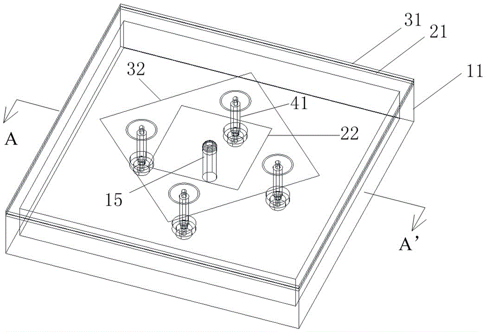
Figure 1 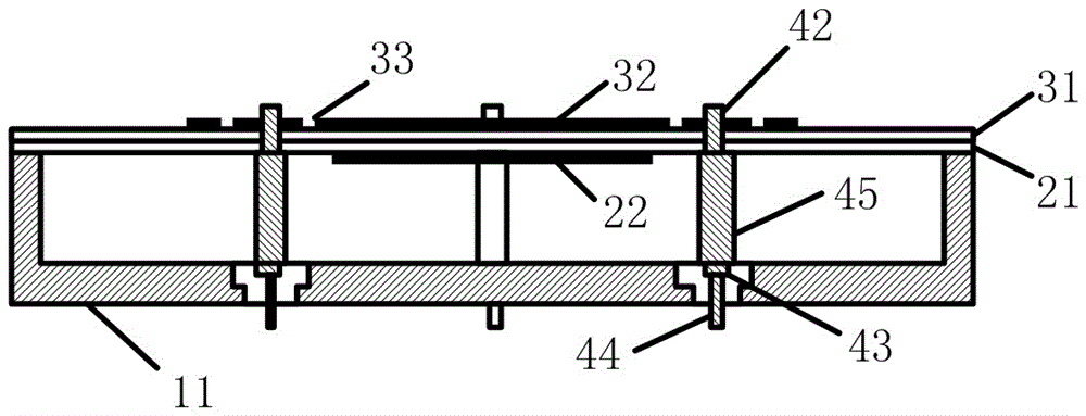
Figure 2 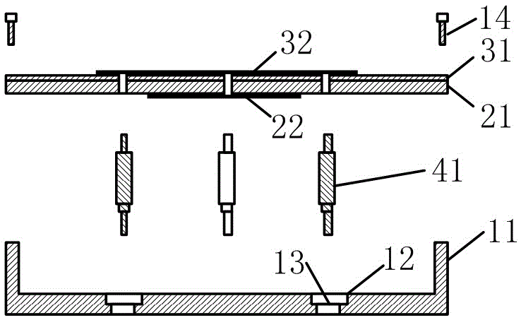
Figure 3
Abstract
Description
technical field
[0001] The invention belongs to the field of microwave technology, and can also be used in the fields of microwave communication, modern radar systems, electronic equipment, etc., and specifically relates to a dual-polarization broadband antenna. Background technique
[0002] Antenna is one of the most important components of systems such as wireless broadcasting, wireless communication and wireless detection. As the core of wireless technology, the structure and characteristics of the antenna system determine the working performance of the entire system to a large extent. With the rapid development of active phased array technology, radar and other systems have higher and higher requirements for frequency bandwidth and scanning angle, which also puts forward more and more requirements for the function and performance of the antenna.
[0003] Microstrip patch antennas are widely used in antenna design because of their light weight, small size, low cost, and l...
Examples
Embodiment 1
[0029] A dual-polarized broadband antenna with low cross-section and low cross-polarization, the working frequency is 1.0-1.9GHz, the polarization mode is horizontal polarization and vertical polarization, and the free-space wavelength of the center frequency point lambda 0 About 207mm.
[0030] see figure 1 A dual-polarized broadband antenna with low cross-section and low cross-polarization includes a rectangular flat box-shaped resonant cavity 11 with an open top, an upper microstrip plate 31, a lower microstrip plate 21, four feeding probes 41 and the same Shaft medium 13; the cavity length and width of the resonance cavity 11 are both 122 mm, and the cavity depth is 15 mm.
[0031] see figure 2 with image 3 , the upper microstrip board 31 and the lower microstrip board 21 are overlapped and glued up and down and mounted on the top opening of the resonant cavity 11, and the edges are fixed with screws 14. The material of the upper microstrip plate 31 and the lower f...
Embodiment 2
[0040] see Figure 9 , an antenna array composed of 3 antenna units, the distance between the centers of adjacent antenna units is 121 mm; the metal wall thickness between the resonant cavities 11 of adjacent antennas is 6 mm. The designed working bandwidth of this antenna array is 15%, so a single-layer radiating microstrip board is used, that is, only the upper layer of microstrip board 31 and the upper layer of copper foil patch 32 are provided, without the need for the lower layer of microstrip board 21 and the lower layer of copper foil patch twenty two.
[0041] see Figure 10 , sx1, sx2, sx3 are the relative distances between the two feeding points in the horizontal polarization direction on the radiating microstrip board of the 1st, 2nd, and 3rd antenna elements, respectively, sy1, sy2, sy3 are the relative distances between the two feed points in the vertical polarization direction on the radiating microstrip board of the first, second, and third antenna elements...