
Over-temperature protection LED driving power source
A technology of LED driving and over-temperature protection, applied in the field of lighting, can solve the problems of blocked air inflow, affecting service life, short-circuit heat dissipation, etc., and achieves the effect of long service life, improved practicability and good stability
Patent Information
- Authority / Receiving Office
- CN · China
- Patent Type
- Applications(China)
- Current Assignee / Owner
- Publication Date
- 2017-11-17
- Estimated Expiration
- Not applicable · inactive patent
Smart Images
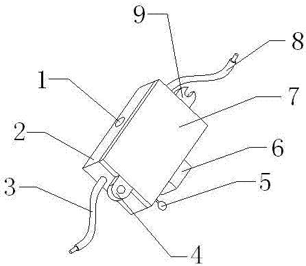
Figure 1 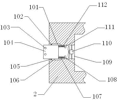
Figure 2 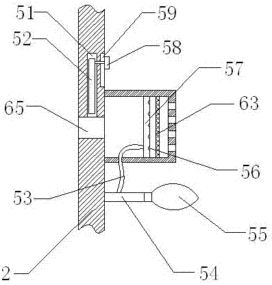
Figure 3
Abstract
Description
technical field
[0001] The invention is an over-temperature protection LED drive power supply, which belongs to the technical field of lighting. Background technique
[0002] The LED drive power supply is a voltage converter that converts the power supply into a specific voltage and current to drive the LED to emit light. Usually: the input of the LED drive power supply includes high-voltage power frequency AC (that is, mains power), low-voltage DC, high-voltage DC, low-voltage high-voltage frequency AC (such as the output of an electronic transformer), etc. The output of the LED drive power supply is mostly a constant current source that can change the voltage with the change of the LED forward voltage drop value.
[0003] In the prior art, there are still many deficiencies in the LED drive power supply. During the heat dissipation process, the dust and moisture in the air cannot be filtered, causing the dust and moisture to enter the power supply, resulting in short circu...
Examples
Embodiment Construction
[0021] In order to make the technical means, creative features, goals and effects achieved by the present invention easy to understand, the present invention will be further described below in conjunction with specific embodiments.
[0022] see Figure 1-Figure 4 , the present invention provides a technical solution: an over-temperature protection LED drive power supply, including a device main body, an automatic shut-off mechanism 1, a back-blowing dust cleaning mechanism 5, and an air filter mechanism 6. The device main body includes a housing 2, a lead wire 3. Fixing ear 1 4, bottom plate 7, pin wire 2 8 and fixing ear 2 9, housing 2 is assembled on the upper end surface of base plate 7, pin wire 1 3 is assembled on the front surface of housing 2, pin wire 2 8 is assembled On the rear end face of the housing 2, the first fixed ear 4 is installed in the middle of the front end of the bottom plate 7, and the second fixed ear 9 is installed in the middle of the rear end of the...