
Abandoned liquid crystal display panel shear crusher
A liquid crystal panel and crusher technology, which is applied in grain processing and other directions, can solve the problems of large-scale, industrialization, high-efficiency recycling of liquid crystal panels, and the inability to meet the recycling needs of liquid crystal panels, and achieves small meshing area, less heat, and friction. short distance effect
Patent Information
- Authority / Receiving Office
- CN · China
- Current Assignee / Owner
- Publication Date
- 2017-12-01
Smart Images
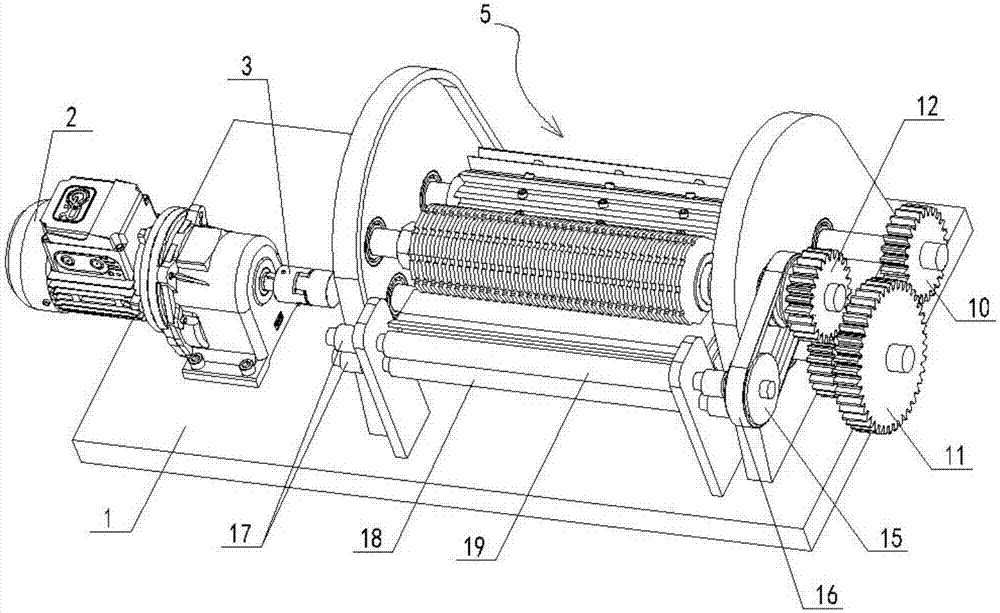
Figure 1 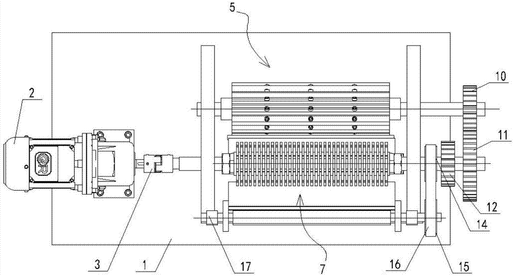
Figure 2 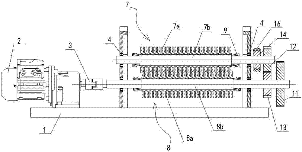
Figure 3
Abstract
Description
technical field
[0001] The invention relates to a shredder, and more specifically relates to a device capable of shearing and shredding waste liquid crystal panels. Background technique
[0002] Liquid Crystal Display, or LCD, has the characteristics of small size, light weight, low energy consumption, and excellent display effect, and has been widely used in people's daily production and life. With the advancement of technology and the continuous improvement of people's living standards, the life cycle of liquid crystal displays is getting shorter and shorter. In recent years, a large number of liquid crystal displays have been eliminated or discarded. The liquid crystal panels contain high-value liquid crystal materials, rare and precious metal indium, and high-quality glass.
[0003] Liquid crystal is an indispensable polymer display material in the LCD panel. It is poured between two ITO glasses of the LCD screen. ITO refers to Indium-Tin Oxide, that is, indium-tin oxid...
Examples
Embodiment Construction
[0030]The shearing and shredding machine for waste liquid crystal panels in this embodiment includes a biaxial shearing mechanism, a rotary cutting mechanism and a feeding mechanism.
[0031] like figure 1 and image 3 As shown, the biaxial shearing mechanism has a lower cutter shaft 8b and an upper cutter shaft 7b arranged in parallel, and the lower cutter shaft 8b and the upper cutter shaft 7b are supported by a support plate and a rolling bearing 4 arranged on the support plate; The output shaft of the output shaft is directly connected with the lower cutter shaft 8b through the coupling 3, and is used to drive the rotation of the lower cutter shaft 8b; the lower cutter shaft 8b and the upper cutter shaft 7b realize gear transmission through a pair of meshing gears, and the pair of meshing gears are respectively The lower cutter shaft inner gear 13 fixedly arranged on the shaft end of the lower cutter shaft 8b, and the upper cutter shaft gear 12 fixedly arranged on the sha...