
Thin oil lubrication heating system of cross-cutting production line
A thin oil lubrication and heating system technology, applied in the direction of lubricating parts, engine lubrication, engine components, etc., can solve problems such as affecting heating effect, aggravating oil, oil temperature unevenness, etc., to reduce equipment investment costs, improve Heating capacity and space saving effect
Patent Information
- Authority / Receiving Office
- CN · China
- Current Assignee / Owner
- Publication Date
- 2018-02-23
- Estimated Expiration
- Not applicable · inactive patent
Smart Images
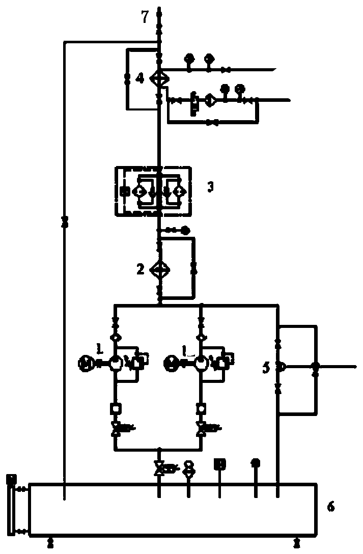
Figure 1
Abstract
Description
technical field
[0001] The invention relates to a thin oil lubrication heating system for a cross-cutting production line. Background technique
[0002] Thin oil lubrication system is mainly composed of oil tank, heater, screw pump device, sewage gear pump, filter, pressure controller, cooler, temperature controller, pneumatic valve frame and pressure tank. The thin oil lubrication system is arranged with two oil tanks, one for use and one for standby. The lubricating oil is sucked out from the oil tank by the screw pump, delivered to the lubrication point of the equipment through the duplex filter and the cooler, after lubricating and cooling the equipment, it flows back to the oil tank through the oil return connection to complete a cycle. The pressure tank plays a role in stabilizing the voltage and providing instantaneous protection to the key equipment running at high speed in case of sudden accidents such as power failure. The system adopts the way of oil tank heatin...
Examples
Embodiment 1
[0014] A thin oil lubrication heating system for a cross-cutting production line according to the present invention includes an oil pipeline 7, the output end of the oil pipeline 7 is connected to the oil tank 6 through a double cylinder filter 3 and a pipeline heater 2, and the oil pipeline 7 A plate cooler 4 is provided between the output end of the liquid pipeline 7 and the duplex filter 3 ; a pneumatic pressure regulating valve 5 is provided between the pipeline heater 2 and the oil tank 6 .
[0015] Both valves are respectively connected with the pneumatic pressure regulating valve 5 .
[0016] The filtration accuracy of the duplex filter 3 in this embodiment is 80 μ.
[0017] The volume of the mailbox described in this embodiment is 5 cubic meters.
[0018] The oil flows out from the oil pipeline 7, passes through the pipeline heater 2, and realizes the heating effect by exchanging heat with the pipeline heater 2, and then enters the oil tank 6 after being filtered by t...
Embodiment 2
[0020] This embodiment is basically the same as Embodiment 1, the difference is that this embodiment is provided with two oil passages between the pipeline heater 2 and the oil tank 6, and each oil passage is provided with a valve, each of which Each oil channel is provided with a screw pump 1, and each screw pump 1 is connected with a motor, and the flow rate of the screw pump 1 is 206 liters per minute. In this embodiment, two screw pumps 1 divide the flow of the liquid in the pipeline heater 2 and then flow into the oil tank 6, which avoids a large loss of oil temperature and relieves the pipeline pressure.