
Carbon electrode perovskite solar battery and preparation method thereof
A solar cell and perovskite technology, which is applied to circuits, electrical components, and electrical solid devices, can solve problems such as perovskite corrosion, and achieve the effect of reducing corrosion and drying time
Patent Information
- Authority / Receiving Office
- CN · China
- Current Assignee / Owner
- Publication Date
- 2018-04-13
Smart Images
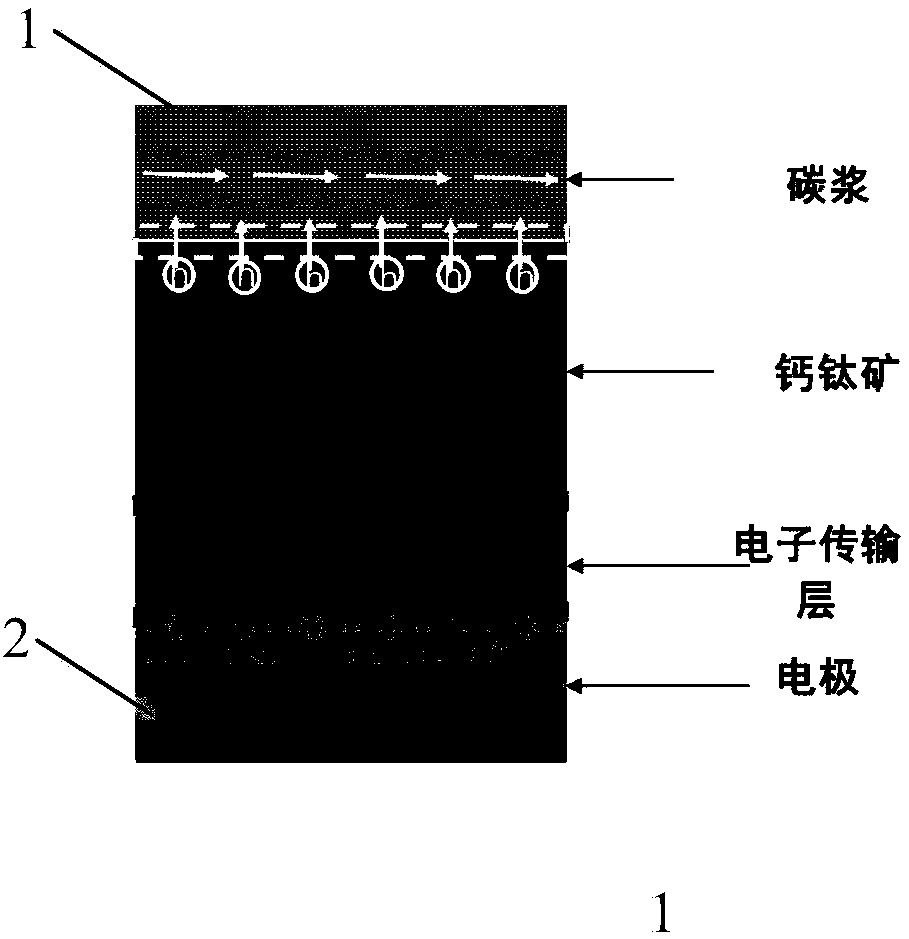
Figure 1 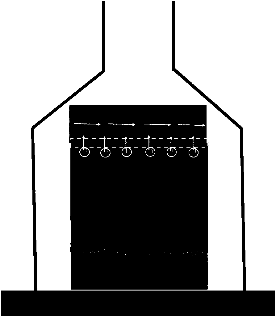
Figure 2 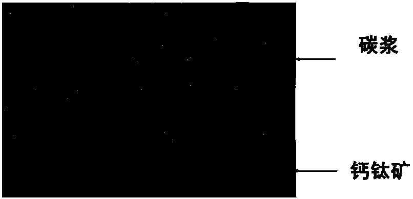
Figure 3
Abstract
Description
technical field
[0001] The invention relates to the fields of material science technology, thin film preparation technology and solar cell preparation technology, in particular to a carbon electrode perovskite solar cell and a preparation method thereof. Background technique
[0002] Since perovskite cells achieved an efficiency of 3.9% in 2009, this type of cell has aroused heated discussions and research. Currently the highest certified efficiency is 22.1%. However, conventional perovskite solar cells with HTM metal electrodes still have many problems. Due to the existence of HTM such as Spiro-MeOTAD, the battery stability is poor and expensive; noble metal electrodes, such as Ag, are expensive and will react with perovskite; noble metal Au electrodes are expensive and their preparation process also limits perovskite. Large-scale and low-cost continuous production of mining batteries. Carbon materials are ideal substitutes for noble metal electrodes due to their abundan...
Examples
Embodiment 1
[0056] 1. On the ITO substrate, spin-coat TiO 2 Precursor, sintered at 500 degrees for half an hour to prepare dense TiO 2 Electron transport layer;
[0057] 2. In dense TiO 2 A layer of perovskite precursor was spin-coated on the electron transport layer and dried to prepare MAPbI 3 perovskite thin film.
[0058] 3. On the dense perovskite film, use a scraper method to scrape a layer of commercial carbon slurry with a thickness of about 15 μm whose solvent is isophorone, then heat on the surface of the carbon slurry, cool the ITO side, and dry it under a pressure of 100Pa , to accelerate the volatilization of the solvent, that is, to obtain a carbon electrode perovskite solar cell.
[0059] Test and record the cross-sectional morphology of the carbon film, such as Figure 3-1 , Figure 3-2 As shown, the perovskite morphology remained intact and no corrosion occurred. Battery performance such as Figure 3-3 shown
Embodiment 2
[0061] 1. On the ITO substrate, spin-coat TiO 2 Precursor, sintered at 500 degrees for half an hour to prepare dense TiO 2 Electron transport layer;
[0062] 2. In dense TiO 2 A layer of perovskite precursor was spin-coated on the electron transport layer and dried to prepare FAPbI 3 perovskite thin film.
[0063] 3. On the hole transport layer, use a scraper method to scrape a layer of commercial carbon slurry with a thickness of about 20 μm whose solvent is butyl acetate, then heat on the surface of the carbon slurry, cool the ITO side, and dry it under a pressure of 100 Pa to make the solvent Accelerate volatilization to obtain carbon electrode perovskite solar cells.
Embodiment 3
[0065] 1. On the ITO substrate, spin-coat TiO 2 Precursor, sintered at 500 degrees for half an hour to prepare dense TiO 2 Electron transport layer;
[0066] 2. In dense TiO 2 A layer of perovskite precursor was spin-coated on the electron transport layer and dried to prepare FAPbI 3 Perovskite film, spin-coated with a layer of P3HT hole transport layer.
[0067] 3. On the hole transport layer, use a scraper method to scrape a layer of commercial carbon slurry with a thickness of about 20 μm as the solvent of butyl acetate, then heat the surface of the carbon slurry, cool the ITO side, and dry it under a pressure of 10 Pa to make the solvent Accelerate volatilization to obtain carbon electrode perovskite solar cells.