
Soil loosening machine used for garden seedling planting
A technology for scarifiers and seedlings, which is applied in the fields of gardening, application, agricultural machinery and implements, etc., can solve the problems of mosquito repelling, inconvenient supply of electric energy, etc., and achieve the effect of good soil scarification
Patent Information
- Authority / Receiving Office
- CN · China
- Patent Type
- Applications(China)
- Current Assignee / Owner
- Publication Date
- 2018-09-04
- Estimated Expiration
- Not applicable · inactive patent
Smart Images
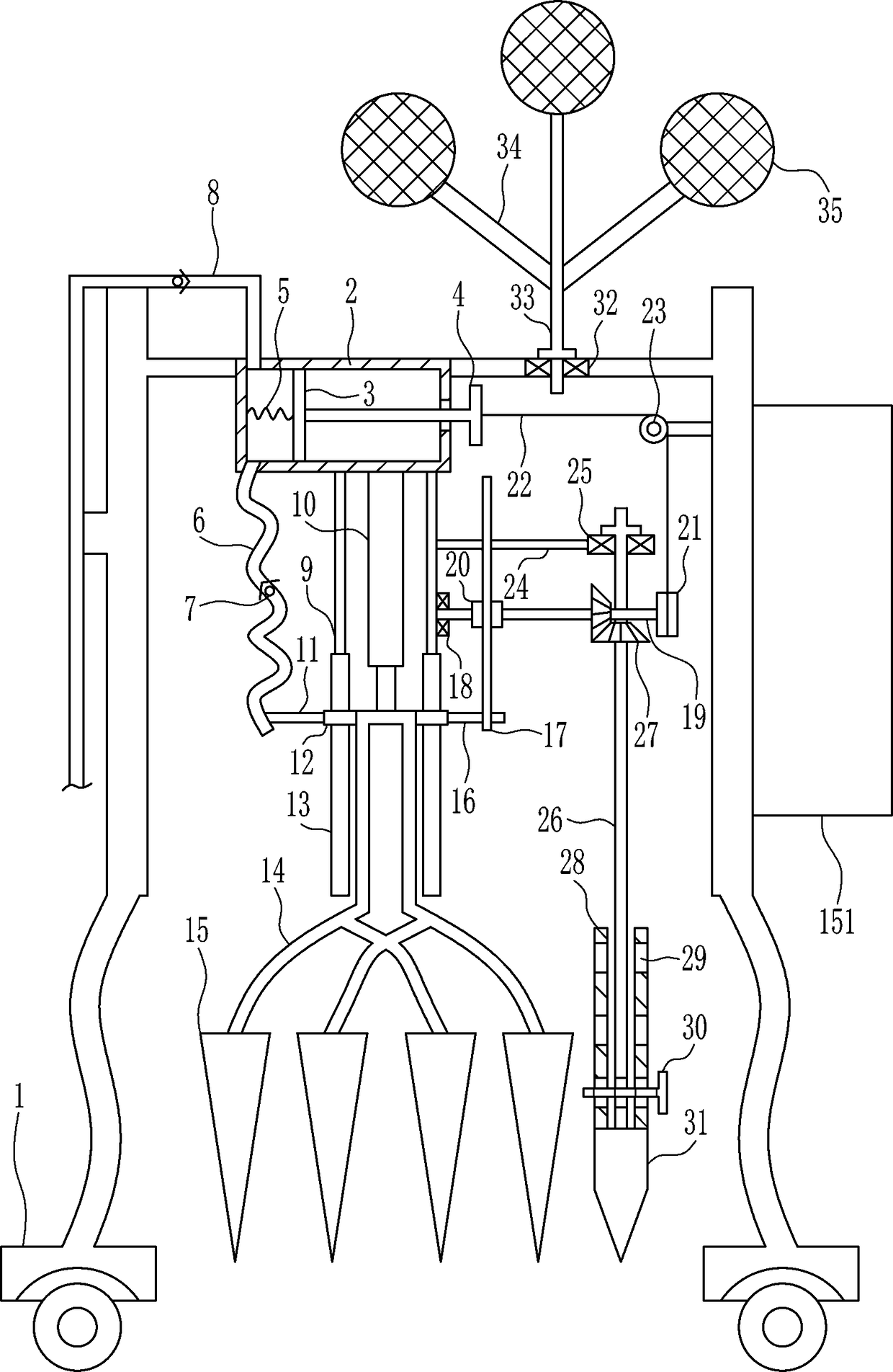
Figure 1 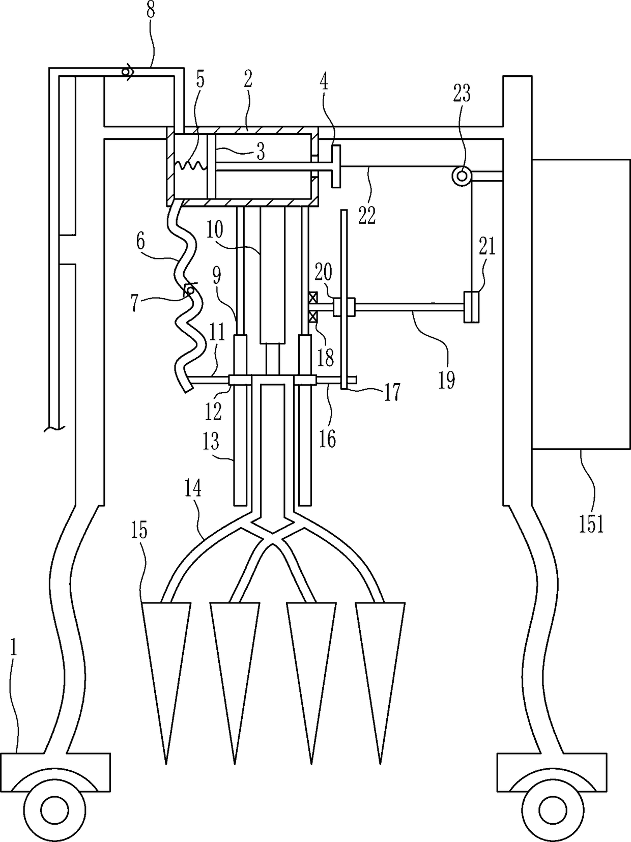
Figure 2 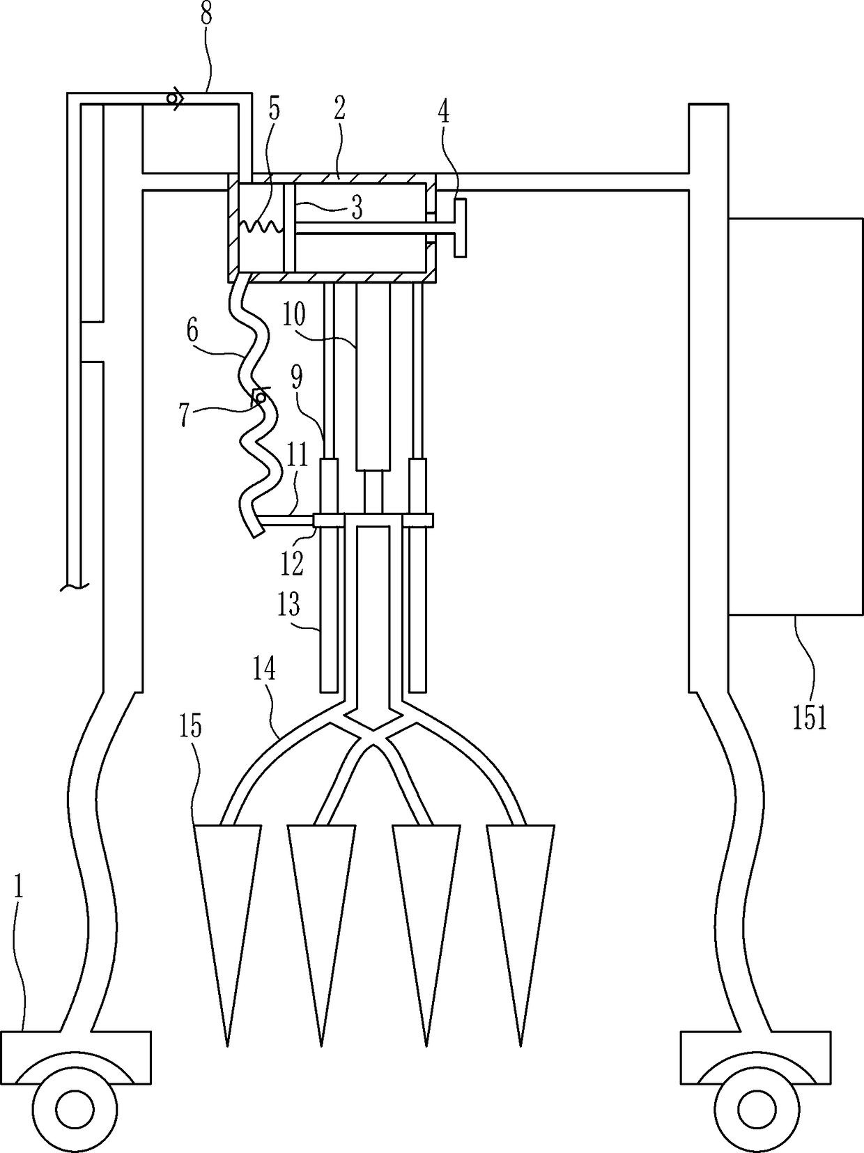
Figure 3
Abstract
Description
Technical field
[0001] The invention relates to a soil scarifier, in particular to a soil scarifier for garden planting seedlings. Background technique
[0002] Applying engineering technology and artistic methods in a certain area, through the transformation of terrain (or further building mountains, stacking rocks, water management), planting trees and flowers, building buildings and arranging garden roads to create beautiful natural environments and recreational areas, It is called a garden. It is unique among traditional Chinese architecture, and it is the classical garden architecture that has made major achievements.
[0003] Before planting garden seedlings, it is necessary to loosen the soil. At present, people loosen the soil manually, which is prone to accidents. Most of the existing soil scarifiers for garden planting seedlings cannot automatically moisten the soil intermittently and cannot repel mosquitoes. Kill mosquitoes.
[0004] Therefore, it is urgent to develop a...
Examples
Embodiment 1
[0028] A soil ripper for planting seedlings in gardens, such as Figure 1-5 As shown, it includes a movable frame 1, a cylinder 2, a piston 3, a first push rod 4, a spring 5, a water outlet pipe 6, a one-way valve 7, a water inlet pipe 8, a fixed rod 9, an electric push rod 10, and a first horizontal The rod 11, the sliding sleeve 12, the guide rail 13, the connecting rod 14, the first conical block 15 and the battery 151, the top left side of the movable frame 1 is embedded with a cylinder 2 which is provided with a piston 3 and the right piston 3 A first push rod 4 is connected to the middle of the side, the first push rod 4 passes through the right side of the cylinder 2, a spring 5 is connected between the middle left of the piston 3 and the middle left of the cylinder 2, and the bottom of the cylinder 2 is connected to the left There is a water outlet pipe 6, which is connected to the bottom of the cylinder block 2. Both the outlet pipe 6 and the water inlet pipe 8 are pro...
Embodiment 2
[0030] A soil ripper for planting seedlings in gardens, such as Figure 1-5 As shown, it includes a movable frame 1, a cylinder 2, a piston 3, a first push rod 4, a spring 5, a water outlet pipe 6, a one-way valve 7, a water inlet pipe 8, a fixed rod 9, an electric push rod 10, and a first horizontal The rod 11, the sliding sleeve 12, the guide rail 13, the connecting rod 14, the first conical block 15 and the battery 151, the top left side of the movable frame 1 is embedded with a cylinder 2 which is provided with a piston 3 and the right piston 3 A first push rod 4 is connected to the middle of the side, the first push rod 4 passes through the right side of the cylinder 2, a spring 5 is connected between the middle left of the piston 3 and the middle left of the cylinder 2, and the bottom of the cylinder 2 is connected to the left There is a water outlet pipe 6, which is connected to the bottom of the cylinder block 2. Both the outlet pipe 6 and the water inlet pipe 8 are pro...
Embodiment 3
[0033] A soil ripper for planting seedlings in gardens, such as Figure 1-5 As shown, it includes a movable frame 1, a cylinder 2, a piston 3, a first push rod 4, a spring 5, a water outlet pipe 6, a one-way valve 7, a water inlet pipe 8, a fixed rod 9, an electric push rod 10, and a first horizontal The rod 11, the sliding sleeve 12, the guide rail 13, the connecting rod 14, the first conical block 15 and the battery 151, the top left side of the movable frame 1 is embedded with a cylinder 2 which is provided with a piston 3 and the right piston 3 A first push rod 4 is connected to the middle of the side, the first push rod 4 passes through the right side of the cylinder 2, a spring 5 is connected between the middle left of the piston 3 and the middle left of the cylinder 2, and the bottom of the cylinder 2 is connected to the left There is a water outlet pipe 6, which is connected to the bottom of the cylinder block 2. Both the outlet pipe 6 and the water inlet pipe 8 are pro...