
Projector placing frame for teaching
A technology for placing racks and projectors, applied to projection devices, optics, instruments, etc., can solve the problems of inaccurate angle adjustment, cumbersome operation, and poor practicability, so as to avoid excessive temperature and make the adjustment work accurate and convenient , the effect of convenient operation
Patent Information
- Authority / Receiving Office
- CN · China
- Patent Type
- Applications(China)
- Current Assignee / Owner
- Publication Date
- 2018-09-14
- Estimated Expiration
- Not applicable · inactive patent
Smart Images
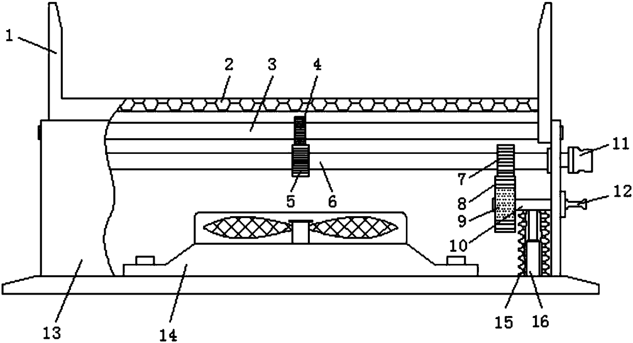
Figure 1 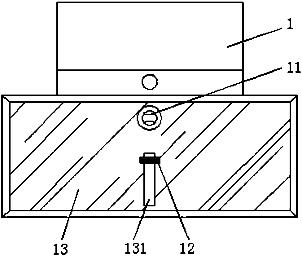
Figure 2 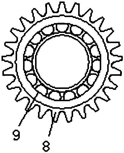
Figure 3
Abstract
Description
technical field
[0001] The invention relates to the technical field of teaching equipment, in particular to a teaching projector placement rack. Background technique
[0002] A projector, also known as a projector, is a device that can project images or videos onto a screen. It can be connected to a computer, VCD, DVD, BD, game console, DV, etc. through different interfaces to play the corresponding video signal. Projectors are currently widely used in homes, offices, schools, and entertainment venues. According to different working methods, there are different types such as CRT, LCD, and DLP.
[0003] At present, the projector stand for teaching is simple in structure, single in function, not strong in practicability, inaccurate in angle adjustment process, and cumbersome in operation process. Contents of the invention
[0004] The purpose of the present invention is to solve the shortcomings in the prior art, and propose a projector placement rack for teaching. [0005...
Examples
Embodiment Construction
[0021] The following will clearly and completely describe the technical solutions in the embodiments of the present invention with reference to the accompanying drawings in the embodiments of the present invention. Obviously, the described embodiments are only some, not all, embodiments of the present invention.
[0022] refer to Figure 1-3 , a projector placement rack for teaching, comprising a hollow plate 2 and a fixed housing 13, and the hollow plate 2 is movably connected to the fixed shell 13, and the four sides of the top of the hollow plate 2 are vertically welded with a limit plate 1, The bottom of the hollow plate 2 is provided with a fixed shaft 3, and the center position of the fixed shaft 3 is welded with a first gear 4, and the bottom of the first gear 4 is meshed with a second gear 5, and the second gear 5 is connected to the fixed shaft through the rotating shaft 6. The inner surface walls on both sides of the housing 13 are movably connected, the third gear 7...