
White corundum block waste heat utilization system
A white corundum and waste heat technology, applied in the field of white corundum block waste heat utilization system, can solve problems such as non-compliance and unfavorable health of staff
Patent Information
- Authority / Receiving Office
- CN · China
- Patent Type
- Applications(China)
- Current Assignee / Owner
- Publication Date
- 2018-11-30
Smart Images
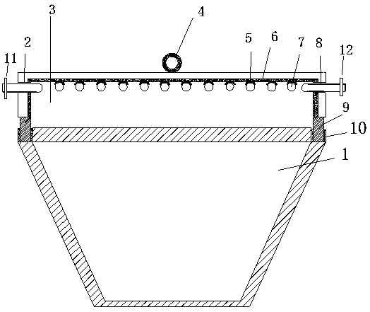
Figure 1 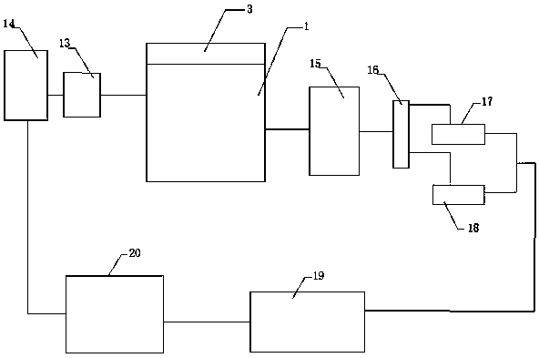
Figure 2 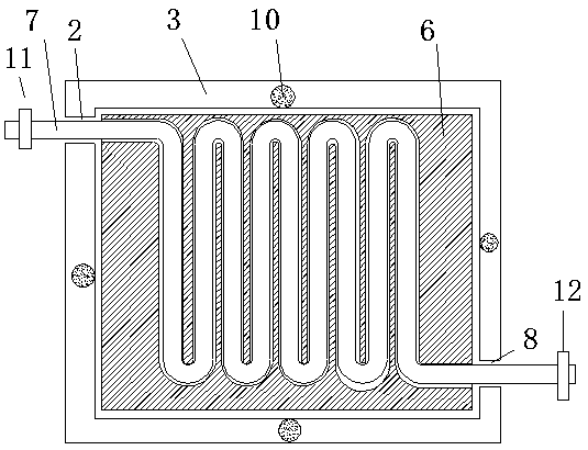
Figure 3
Abstract
Description
technical field
[0001] The invention belongs to the technical field of industrial waste heat reuse, and in particular relates to a white corundum block waste heat utilization system. Background technique
[0002] Usually, the smelted white corundum needs to be put into the cooling pool for cooling, and a lot of waste heat will be generated during the cooling process. There is no preheating recovery technology in the existing technology, and a lot of heat is emitted, especially in summer. It will make the working environment extremely stuffy, which is not good for the health of the staff, and does not conform to the current concept of energy saving, emission reduction and low-carbon production advocated by the state. Contents of the invention
[0003] The purpose of the present invention is to overcome the deficiencies of the prior art, and provide a waste heat utilization system with simple structure, easy implementation, and advanced concept, which can improve the working...
Examples
Embodiment Construction
[0018] The technical solution of the present invention will be further described below in conjunction with the accompanying drawings.
[0019] like figure 1 - Shown in 4: a white corundum block waste heat utilization system, including a cooling pool 1, the cooling pool 1 is a quadrangular pyramid structure with a large upper part and a smaller lower part, and a heat collecting cover is arranged above the cooling pool 1 3. The heat collecting cover 3 is a square frame structure, and the upper left side of the heat collecting cover 3 is provided with a pipe hole A2 for installing a quick heat pipe 7, and the fast heat water pipe 7 penetrates through the pipe hole A2 In the heat collecting cover 3, the part of the fast heat water pipe 7 placed in the heat collecting cover 3 is coiled on the upper wall of the heat collecting cover 3, and is led out through the pipe hole B8 provided under the right side of the heat collecting cover 3; The inner upper wall and the inner side wall o...