
Energy-saving environment-friendly intelligent filtering water dispenser device
An energy-saving, environmentally friendly, water dispenser technology, applied in beverage preparation devices, filtration treatment, water/sewage treatment, etc., can solve the problems of inability to isolate dust, water resources pollution, and easy rollover of the water dispenser, and achieve poor isolation. , the effect of solving center instability
Patent Information
- Authority / Receiving Office
- CN · China
- Patent Type
- Applications(China)
- Current Assignee / Owner
- Publication Date
- 2019-01-04
- Estimated Expiration
- Not applicable · inactive patent
Smart Images
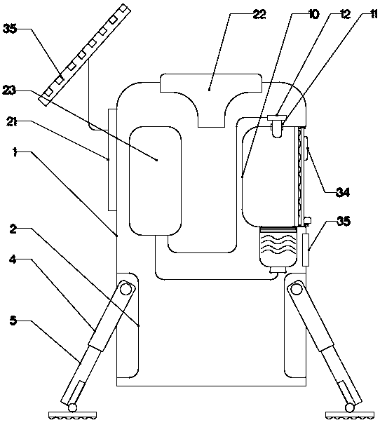
Figure 1 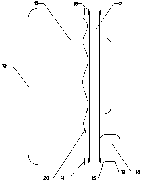
Figure 2 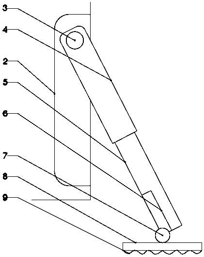
Figure 3
Abstract
Description
technical field
[0001] The invention relates to the related fields of household electrical appliances, in particular to an energy-saving and environment-friendly intelligent filtering water dispenser device. Background technique
[0002] The position of the present water dispenser is basically all fixed, but if it is used outdoors, due to the unevenness of the outdoor ground, the general water dispenser is easy to roll over, and it is generally used in places with poor environment and more dust. The water dispenser cannot isolate the dust, which will cause water resources to be polluted. Contents of the invention
[0003] The purpose of the present invention is to solve the above problems, and to design an energy-saving and environment-friendly intelligent filter water dispenser device.
[0004] To achieve the above object, the technical solution of the present invention is to include a rectangular box, a supporting device is provided under the rectangular box, and the su...
Examples
Embodiment Construction
[0021] The present invention is specifically described below in conjunction with accompanying drawing, as Figure 1-4 As shown, it includes a rectangular box 1, a supporting device is provided under the rectangular box 1, and the supporting device is formed by a rectangular groove located on the lower end side surface of the rectangular box 1 and fixedly connected with the rectangular box 1 in the vertical direction. 12. The pin shaft 3 fixedly connected to the opposite side surface of the upper end of the rectangular groove 12 and the rectangular groove 12. The support rod 4 located on the annular side surface of the pin shaft 13 and one end connected to the pin shaft 13. , the support rod 2 5 that is located on the inner surface of the support rod 4 and is connected with the support rod 1 4 sleeve, the rectangular groove 6 that is fixedly connected with the support rod 2 5 on the lower end side surface of the support rod 2 5, and is located on the side of the rectangular groo...