
Temporary traffic guardrail
A traffic and guardrail technology, applied in the field of guardrails, can solve problems such as smashing pedestrians, being easily blown over, affecting normal use, etc., to achieve the effect of ensuring warning, good guidance, and improving stability
Patent Information
- Authority / Receiving Office
- CN · China
- Current Assignee / Owner
- Publication Date
- 2019-12-24
Smart Images
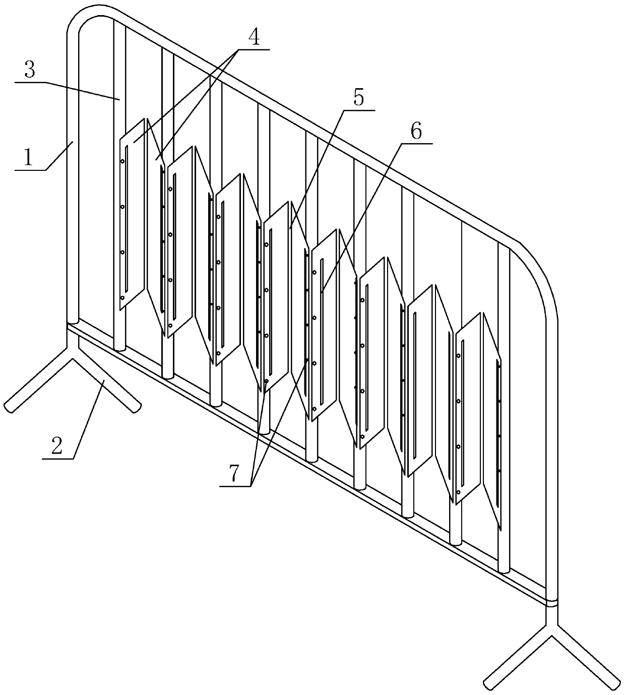
Figure 1 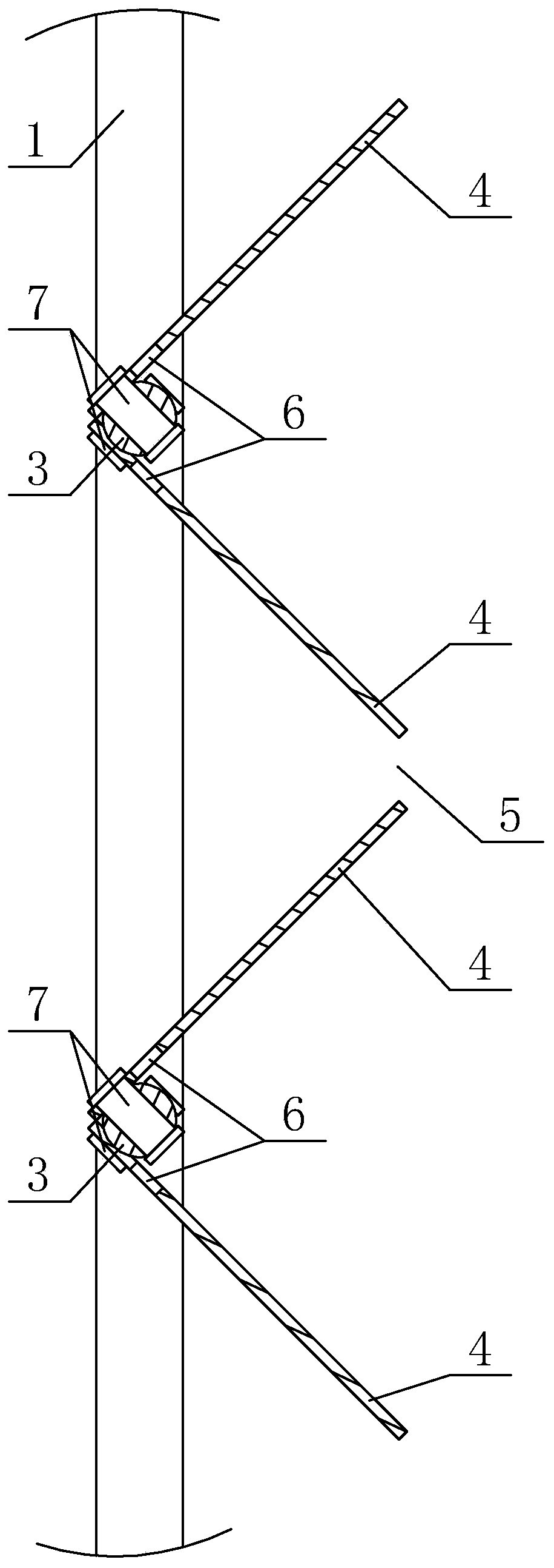
Figure 2 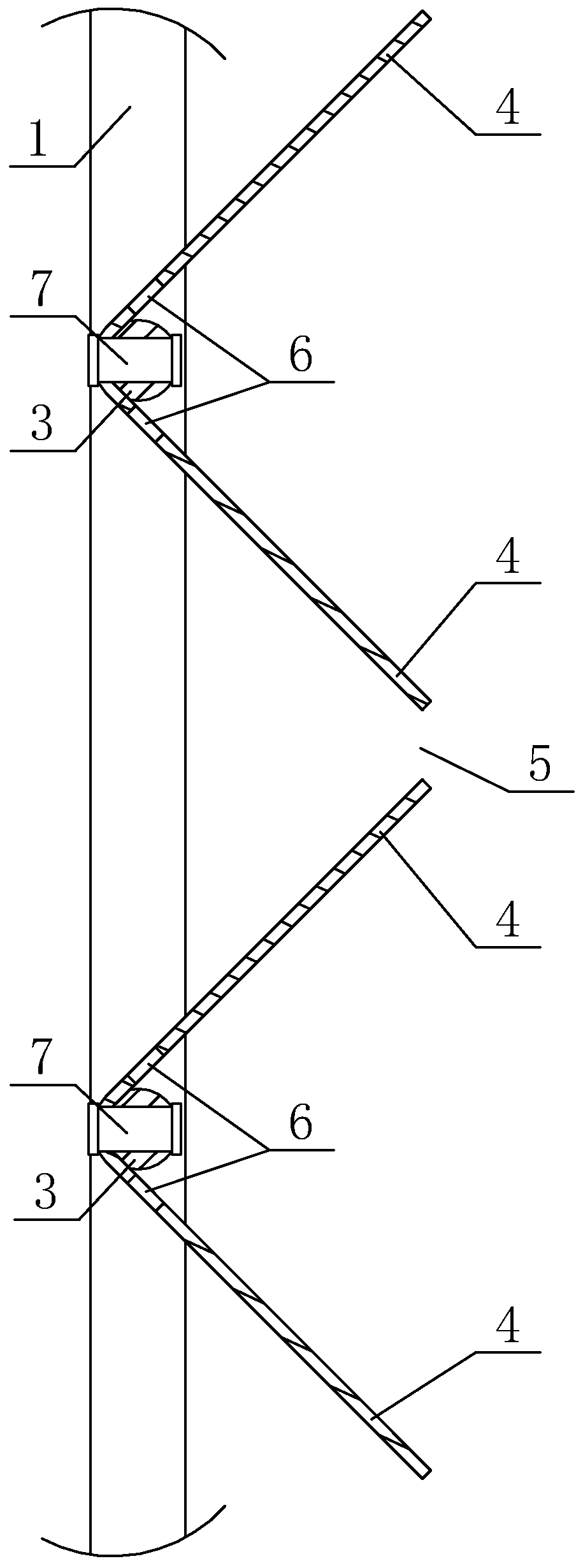
Figure 3
Abstract
Description
technical field
[0001] The invention relates to the field of guardrails, in particular to a temporary traffic guardrail. Background technique
[0002] Traffic guardrails play an important role in urban traffic. They can separate lanes, or block roads, and warn people or vehicles; they can better regulate traffic order.
[0003] Among them, the temporary traffic guardrail is set as a single-piece structure, which is transported and arranged on the road to block traffic when needed; the temporary traffic guardrail of the single-piece structure will be provided with a flat plate-shaped plate structure on the surface of the guardrail for setting warning text and signs. Or advertising, etc.; but because the single-piece structure of the temporary traffic guardrail has no peripheral structure for auxiliary fixing, after the flat board is installed, it will bear a large wind force when it is blown by the wind, and the overall temporary traffic guardrail is easier when the wind is s...
Examples
Embodiment Construction
[0023] Specific embodiments of the present invention will be described in detail below in conjunction with the accompanying drawings.
[0024] Such as Figure 1-7 Shown is a kind of specific embodiment of the temporary traffic barrier of the present invention. This embodiment comprises a square frame 1, a support foot 2 arranged below the square frame 1, and several railings 3 vertically arranged in the square frame 1, some railings 3 are provided with several sub-boards 4, and several sub-boards 4 Arranged on several railings 3 to form a continuous zigzag shape, the angle between sub-boards 4 arranged in a zigzag shape is 60-90 degrees, and an exhaust channel 5 for air circulation is reserved between sub-boards 4 and sub-boards 4 , The side where the sub-board 4 is connected to the railing 3 is provided with exhaust holes 6 for air circulation from top to bottom.
[0025] When the present invention is in use, as figure 1 As shown, the square frame 1, supporting feet 2, and...