
Multi-output multi-voltage-class transplantable multi-stage power electronic converter topological structure
A multi-voltage level, power electronics technology, applied in the direction of high-efficiency power electronic conversion, output power conversion device, and adjustment of electrical variables, can solve the problems of large switching loss, complex mode switch state switching, and difficult to eliminate dead zone effect. Achieve the effects of small required space, high energy utilization rate, and low output harmonics
Patent Information
- Authority / Receiving Office
- CN · China
- Patent Type
- Applications(China)
- Current Assignee / Owner
- Publication Date
- 2020-03-24
- Estimated Expiration
- Not applicable · inactive patent
Smart Images
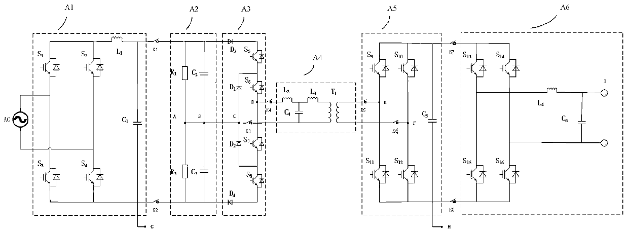
Figure 1 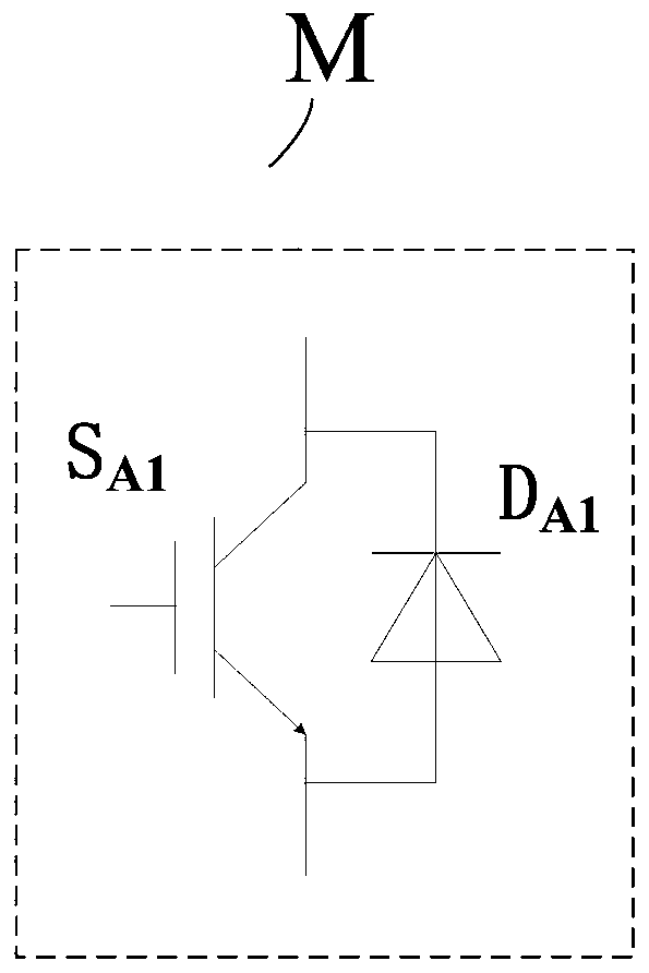
Figure 2 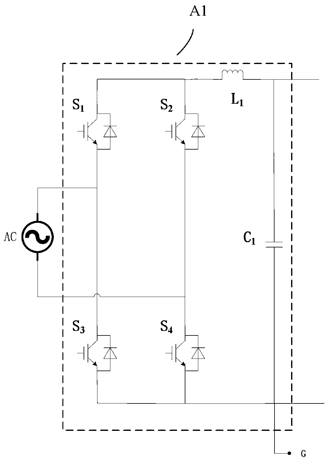
Figure 3
Abstract
Description
technical field
[0001] The invention belongs to the technical field of power electronics, and in particular relates to a multi-level power electronic converter topology structure with multiple outputs and multiple voltage levels that can be transplanted. Background technique
[0002] With the development of power electronic conversion technology, more and more occasions pay more attention to the application of multi-type power supply integrated management. The power conversion system with multiple voltage levels and multiple outputs can be used in high-speed rail power distribution rooms, communication base station power distribution rooms, transmission and transformation Specific implementation areas such as power distribution room. However, in applications with multiple types of power sources, how to comprehensively manage multiple power sources, reduce loss, improve efficiency, and reduce output waveform harmonics are issues that system designers need to consider. [000...
Examples
Embodiment 1
[0077] Such as figure 1 As shown, this embodiment provides a multi-level power electronic converter topology with multiple outputs and multiple voltage levels that can be transplanted, including A1-A6 six groups of electrical modules and K 1 -K 8 Eight dismount switches.
[0078] The first end of the first electrical module A1 is connected to the power supply, and the second end passes through the first disassembly switch K 1 , the second removal switch K 2 connected to the first end of the second electrical module A2;
[0079] The second end of the second electrical module A2 is connected to the first end of the third electrical module A3;
[0080] The second end of the third electrical module A3 passes through the fourth dismounting switch K 4 Connected to the first end of the fourth electrical module A4;
[0081] The second end of the fourth electrical module A4 passes through the fifth dismounting switch K 5 connected to the first end of the fifth electrical module ...
Embodiment 2
[0092] Such as figure 1 As shown, this embodiment provides a multi-output multi-voltage level portable multi-level power electronic converter topology, including six electrical modules A1-A6, eight disassembly switches K with cut-off capability 1 ~K 8 .
[0093] For electrical module A1:
[0094] Module circuit topologies such as image 3 As shown, the first switching device S 1 with the third switching device S 3 , the second switching device S 2 with the fourth switching device S 4 After being connected in series in the same direction, they are sequentially connected to both sides of the power supply side, and the first switching device S 1 , the second switching device S 2 , the third switching device S 3 , the fourth switching device S 4 form an H-bridge with the first inductor L 1 , the first capacitance C 1 Combined into the first electrical module A1;
[0095] The first inductance L 1 The anode is connected to the first switching device S 1 with the sec...
Embodiment 3
[0118] Such as figure 2 As shown, this embodiment provides a multi-output multi-voltage level power electronic converter circuit topology for power conversion systems, including sixteen switching devices S 1 -S 16 , six bus capacitors C 1 -C 6 , eight dismantling switches K with cut-off capability 1 -K 8 , four inductors L 1 -L 4 , two grading resistors R 1 , R 2 , four on-off devices (diodes) D 1 -D 4 , an adjustable transformer T 1 .
[0119] The circuit topology consists of a first switching device S 1 , the second switching device S 2 , the third switching device S 3 , the fourth switching device S 4 with the first inductance L 1 , the first capacitance C 1 Composed of 1 road (shown in the area ① in the figure);
[0120] also included by the first capacitor C 2 , the third capacitor C 3 , the first resistor R 1 , the second resistance R 2 , the fifth switching device S 5 , the sixth switching device S 6 , the seventh switching device S 7 , the eig...