
T-shaped sliding rail
A technology of slide rails and sliders, which is applied to T-shaped slide rails. It can solve the problems of unable to control the moving speed of the slider on the slide rail, unable to stop, lack of limit device, etc., to achieve the effect of enhancing practicability, optimizing use and expanding the scope of application
Patent Information
- Authority / Receiving Office
- CN · China
- Current Assignee / Owner
- Publication Date
- 2020-04-14
- Estimated Expiration
- Not applicable · inactive patent
Smart Images
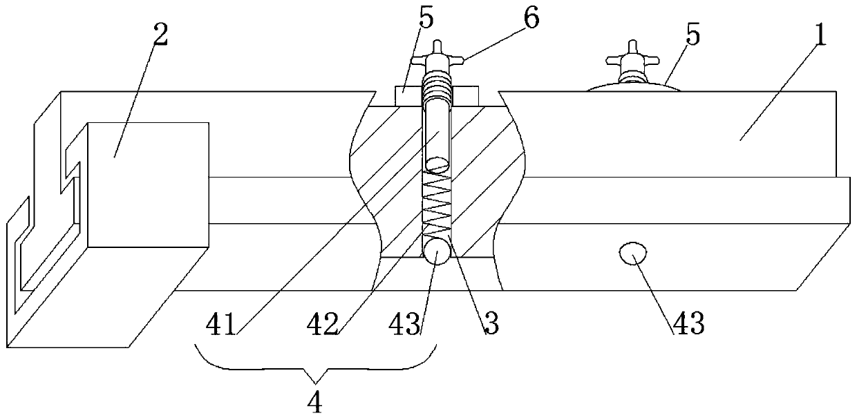
Figure 1 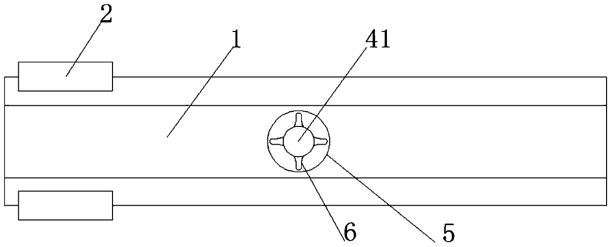
Figure 2
Abstract
Description
Technical field
[0001] The present invention relates to the technical field of slide rail equipment, in particular to a T-shaped slide rail. Background technique
[0002] The T-shaped slide rail structure is a device that is fixed on a certain device for the sliding connection of the slider. The T-shaped slide rail is usually a grooved or curved guide rail. The slider is usually driven by a motor to control the slider. The existing T-shaped slide has no force adjustment device between the slide and the chute, and cannot adjust the force between the slide and the chute, so the speed of the slide cannot be controlled; and the existing T-type The slide rail lacks a limit device and cannot stop when the slider slides to a specific position on the slide rail. Summary of the invention
[0003] The object of the present invention is to provide a T-shaped slide rail to solve the problem that the existing T-shaped slide rail proposed in the background art lacks a limit device and cannot c...
Examples
Embodiment 1
[0018] See Figure 1-2 This embodiment provides a T-shaped slide rail, including a slide rail 1, a sliding block 2 is slidably connected below the slide rail 1, a through hole 3 is opened inside the slide rail 1, and an internal elastic connection limit device for the through hole 3 4.
[0019] In this design, the slider 2 slides under the slide rail 1. By adjusting the limit device 4, the sliding speed of the slider 2 can be controlled, and by adjusting the limit device 4, the slider 2 can also be suspended from sliding.
Embodiment 2
[0021] See Figure 1-2 , A further improvement is made on the basis of embodiment 1: the limit device 4 includes a limit rod 41, a spring 42 and a metal ball 43, the metal ball 43 is fixedly connected to the bottom of the spring 42, and the spring 42 is fixedly connected to the limit rod 41 bottom of.
[0022] Among them, the spring 42 is in a compressed state, and the spring 42 presses the metal ball 43 downward so that the lower end of the metal ball 43 protrudes from the opening at the lower end of the through hole 3. When the compression degree of the spring 42 is small, the slider 2 passes the position of the metal ball 43 and the inner wall of the slider 2 Squeeze the metal ball 43 upward and decelerate to achieve the deceleration effect of the slider 2. By adjusting the limit lever 41 downward, the force of the limit lever 41 pressing the spring 42 downward increases, which increases the force on the metal ball 43. When the slider 2 passes through the metal ball 43, the s...